www.scheppach.com /
+(49)-08223-4002-99 /
+(49)-08223-4002-58
24 | GB
S1 operating mode (continuous duty)
The noise emission values were measured in ac-
cordance with EN ISO 3744.
Wear hearing protection.
The effects of noise can cause a loss of hearing.
7. Unpacking
• In case of complaints the dealer must be informed
immediately. Subsequent complaints will not be ac-
cepted.
• If possible, store the packaging until the warranty
period has expired.
• Read the operating instructions to make yourself
familiar with the device prior to using it.
• Only use original parts for accessories as well as
for wearing and spare parts. Spare parts are avail-
able from your specialized dealer.
• Specify our part numbers as well as the type and
year of construction of the device in your orders.
8. Attachment
m
IMPORTANT!
You must fully assemble the appliance before
using it for the first time!
You require the following for assembly:
• Open-ended spanner 15 mm (not included in the
scope of supply)
• Open-ended spanner 17 mm (not included in the
scope of supply)
• Open-ended spanner 27 mm (not included in the
scope of supply)
• Allen key 6 mm (not included in the scope of supply)
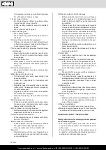
8.1 Fitting the wheels (Fig. C)
Insert the screw (23) through the wheel (14). Now in-
sert the screw (23) through the mount on the pressure
vessel (12). Now fasten the screw (23) with the wash-
er (24), the spring washer (25) and nut (26).
Repeat the process on the other side of the pressure
vessel (12).
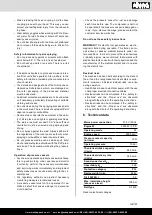
8.2 Fitting the foot (2x) (Fig. D)
Fit the washer (28) on the screw (27). Then insert the
screw (27) through the foot (13). The foot (13) is sub-
sequently fitted on the mount on the pressure vessel
(12).
Fasten the foot (13) with the washer (29), the spring
washer (30) and nut (31).
Repeat the process for the second foot.
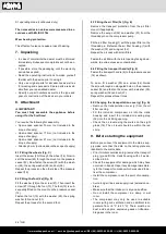
8.3 Fitting the air filter (3x) (Fig. E)
Remove the transport protection from the air filter
mount (if applicable).
Remove the wing nut (32) and washer (33) from the
threaded pin on the compressor pump.
Fit the air filter housing (1) with the paper filter on the
threaded pin. Refasten the air filter housing (1) with
the washer (33) and wing nut (32).
Repeat the process with all air filters.
Fasten the air filter with the inlet opening facing down
-
wards, to avoid excessive contamination.
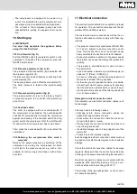
8.4 Fitting the transport handle (Fig. F)
Fasten the transport handle (6) to the pressure vessel
(12) as shown.
To do so, fit a washer (35) on a screw (34). Guide
the screw through an elongated hole on the pressure
vessel (12) and fasten the screw with a washer (35),
spring washer (36) and nut (37).
Repeat this process three times.
8.5 Changing the transportation cover (y) (fig. A)
• Remove the transportation cover (y) from the oil
filter opening.
• Fill the included compressor oil into the crank
housing and insert the included oil sealing plug
(18) into the oil filling opening.
• Check the oil level using the marks on the sight
glass (16). The oil level should be within the red
circle.
9. Before starting the equipment
Before you connect the equipment to the mains sup-
ply make sure that the data on the rating plate are
identical to the mains data.
• Prior to initial commissioning, remove the transport
plug (y) and fill the crank housing with oil as de
-
scribed in 8.5.
• Check the equipment for damage which may have
occurred in transit. Report any damage immediate-
ly to the transport company which was used to de-
liver the compressor.
• Install the compressor near the point of consump-
tion.
• Avoid long air lines and supply lines (extension ca-
bles).
• Make sure that the intake air is dry and dustfree.
• Do not install the compressor in a damp or wet
room.
• The compressor may only be used in suitable
rooms (with good ventilation and an ambient tem-
perature from +5 °C to 40 °C). There must be no
dust, acids, vapors, explosive gases or inflamma
-
ble gases in the room.

