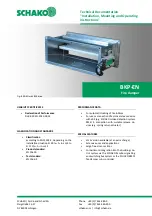
Fire damper BKP-EN
Technical documentation
Models and dimensions
Construction subject to change.
No return possible!
Version: 2020-09-01 | Page 4
MODELS AND DIMENSIONS
Dimensions
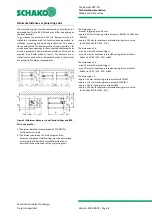
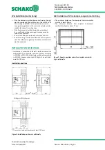
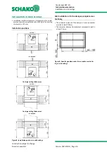
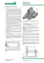
Figure 1: Dimensions BKP-EN
1 Fire damper BKP-EN
2 Damper blade
3 Hand lever
4 Locking profile
5 Release device
6 Fusible link
7 Inspection opening (arranged at bottom) from B ≥ 200,
for B < 200 no inspection opening possible.
x = B/2
200 ≥ B < 600 or
x
~
125 mm
B ≥ 600
y
~
100 mm from the connection flange
8 Actuator unit
9 Profile CW 50/50/06 (with wall thickness = 100 mm, for
larger wall thicknesses, the profiles must be
adapted accordingly)
9.1 Profile CW 75/50/0.6 - 150 profiles
10 Profile UW 50/40/06 (with wall thickness = 100 mm, for
larger wall thicknesses, the profiles must be
adapted accordingly)
10.1 Profile UW 75/40/0.6 - 150 profiles
11 Mineral wool (according to the wall manufacturer's
specifications)
12 Panelling of the lightweight partition wall made of
gypsum-bonded wall boards
12.1 Panelling of the shaft wall made of gypsum-bonded
wall boards.
13 Mortar
14 Mortar anchor (-on site-, 2 drywall screws per B side,
which project approx. 20 mm into the installation
opening, for example TN 3.5x35. Drywall screws arranged
at the ⅓ points.
When using reveals, the length of the drywall screws
must be adjusted accordingly.
15 Reveal, optional (-on site-)
16 Solid ceiling
17 Mounting frame ER-P1 (accessories: loose as mounting kit
or premounted ex works (extra charge)).
17.1 + 17.3 B side Parts 1 and 2
17.2 + 17.4 H side Parts 1 and 2
17.5 Countersunk head screw 4.0 x 60 mm (8 x)
18 Fixing lugs (accessories: mounting frame ER-P1)
19 Drywall screws (on site 2 x / fixing lug;
e.g. ø 3.5 x 35 mm)
19.1 Drywall screws (on site, e.g. ø 3.5 x 35 mm)
19.2 Drywall screws (on site, 2 x / fixing lug; e.g. ø 5.5 x 90 mm)
20 Reveal, circumferential (-on site- 12.5-mm plasterboards)
20.1 Reveal, circumferential (on site, 20 mm plasterboards)
21 Steel cable -galvanised- (accessories: position
indicator type MSZ)
22 Clamping nipple (accessories: position indicator type MSZ)
23 Position indicator (accessories: position indicator type MSZ)
24 False ceiling
25 Manual unlocking disc
26 Fastening screws
27 Locking bolts
28 Fusible link holder
29 Spring return actuator
30 Switch/Lever/Pushbutton
31 Thermoelectric trigger device
32 Duct inside temperature fuse
33 Drywall screws (-on site- e.g. ø 3.5 x 25 mm;
screw spacing
≤
250 mm, but at least 2
screws per side)
34 Horizontal reinforcement e.g. bracket (Ø 8; e ≤ 150 mm)
35 Concrete base (concrete C20/25)
36 Splice bars (Ø 8; e ≤ 500 mm; at least 4 pieces/base)
37 Double-board layer (gypsum-bonded wall boards,
d=20 mm, b=60 mm).

