Fire damper BKP-EN
Technical documentation
Installation in lightweight partition walls with metal posts
Construction subject to change.
No return possible!
Version: 2020-09-01 | Page 13
Wet installation of a fire damper under a solid
ceiling, complete mortar lining
Wet installation under solid ceiling does not constitute a
sliding ceiling connection.
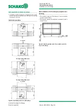
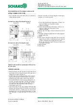
Sectional view under solid ceiling without reveal
Section B-B
Detail X
B
Sectional view under solid ceiling with reveal
Section B-B
Detail Y
B
Figure 15
: Wet installation in lightweight partition wall un-
der solid ceiling
Installation procedure
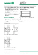
Mount the metal posts and the wall in accordance with the
specifications of the wall manufacturer and the required ex-
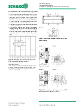
change parts as shown on Figure 13.
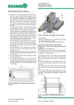
On both B sides of the exchange profiles (at the ⅓ points),
two drywall screws each must be attached to the metal
profiles centrally at the wall as mortar anchor (pos. 14).
Insert the BKP-EN into the wall recess (operating side - ob-
serve the installation dimension of 200 mm). Average out
the circumferential annular gap evenly between the wall
and the BKP-EN. Mount the BKP-EN with the help of
mounting suspensions, etc.
Insert mortar (pos. 13) into the circumferential annular gap
between the housing of the BKP-EN and the circumferential
metal profiles (pos. 10). If reveals (pos. 15) are used, the
opening dimension must be adjusted accordingly. For large
wall thicknesses, a mortar bed depth of 130 mm is suffi-
cient.
After the mortar has set, the mounting aids (mounting sus-
pensions, etc.) must be removed.
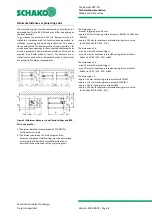
9 Profile CW 50/50/06 (with wall thickness = 100 mm, for
larger wall thicknesses, the profiles must be
adapted accordingly)
10 Profile UW 50/40/06 (with wall thickness = 100 mm, for
larger wall thicknesses, the profiles must be
adapted accordingly)
11 Mineral wool (according to the wall manufacturer's speci-
fications)
12 Panelling of the lightweight partition wall made of gypsum-
bonded wall boards
13 Mortar
14 Mortar anchor (2 drywall screws per B side, which project
approx. 20 mm into the installation opening, for example
TN 3.5x35. Drywall screws arranged at the ⅓ points.
When using reveals, the length of the drywall screws must
be adjusted accordingly.
15 Reveal, optional
16 Solid ceiling

