Line Scan Camera SK6288GKOC-L Manual (06.2015) • shar
ed_CameraContr
ol(2c)_IntegrationTime.indd (06.2015)
18
3 Camera Control and Performing a Scan
SK6288GKOC-L
Instruction Manual
(06.2015)
© 2015
Schäfter + Kirchhoff GmbH
•
Hamburg
Integration Time
The range of intensity distribution of the line scan signal
is affected by the illumination intensity, the aperture
setting and the camera integration time. Conversely, the
aperture setting influences the depth of field as well as
the overall quality of the image and the perceived illumi
-
nation intensity.
The line scan signal is optimum when the signal from the
brightest region of the object corresponds to 95% of the
maximum gain. Full use of the digitalization depth (256 at
8-bit, 4096 at 12-bit) provides an optimum signal sensi
-
tivity and avoids over-exposure (and blooming).
A camera signal exhibiting insufficient gain: the
integration time is too short as only about 50%
of the B/W gray scale is used.
Optimized gain of the camera signal after incre-
asing the integration time, by a factor of 4, to
95% of the available scale.
•
Open the "USB Camera Control" dialog.
SkLineScan USB Camera Control dialog
• The integration time can be set by two vertical sliders
or two input fields in the section "Integration time" of
this dialog. The left slider is for a corser the right for
finer adjustments.
• The current line frequency is displayed in the Line
Frequency status field.
• The adjustment of the integration time in the range of
Integration Control (shutter) with an integration time
shorter than the minimum exposure period does not
change the line frequency. This will be held at
maximum.
• The 'Default' button sets the integration time to the
minimum exposure period in respective of the
maximum line frequency.
• 'Reset' restores the start values.
• 'Cancel' closes the dialog without changes.
• 'OK' stores the integration time values and closes the
dialog.
•
For synchronization settings see
Synchronization of
the Imaging Procedure and the Object Scan
Velocity, p. 19
.
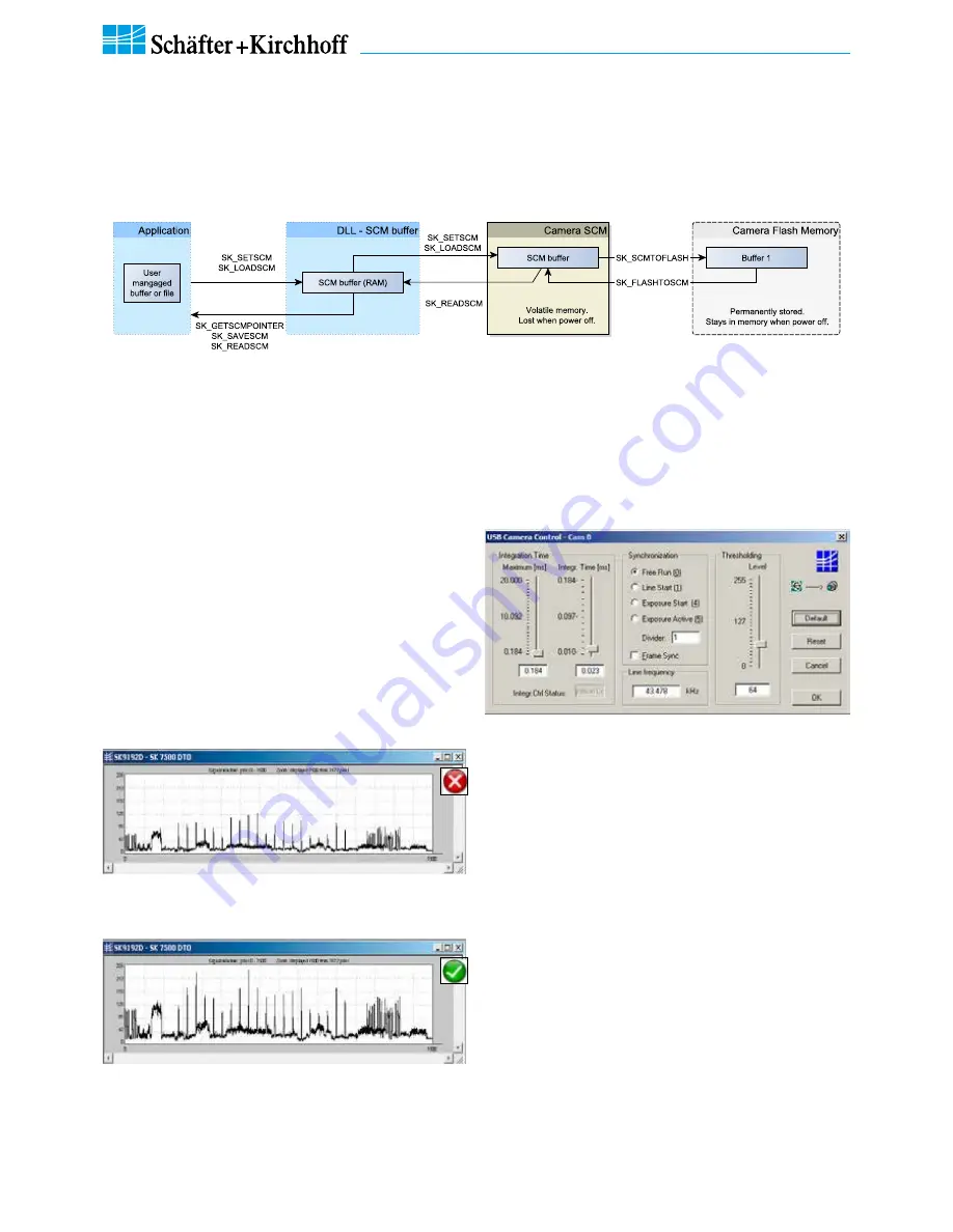
Shading Correction Memories and API Functions
As an alternative to the user dialog, a new shading correction reference signal can also be created by using appli
-
cation programming interface (API) functions. The relationshhip between the storage locations and the related API
functions are shown in the diagram below. The API functions are included in the SK91USB3-WIN software package.
See the
SK91USB3-WIN manual
for details.
Structure of the shading correction memories and the related API functions for memory handling
3 Camera Contr
ol and Performing a Scan


