background image

SK2048GJR-4L

3

2


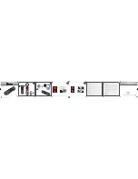
Sample Configuration

1


CCD line scan camera 


SK2048GJR-4L


mounted with

2


Mounting bracket SK5105-L

3


Clamping claws SK5101

4


Focus adapter FA22R-45 (two-piece), 


facilitates adjustment of any rotation angle

5


Enlarging  lens  Apo-Rodagon N 4.0/80

5

4

1

Schäfter + Kir

chhof

f © 2016

  •  Line Scan Camera SK2048GJR-4L Manual (09.2016)  •  shar

ed_Titel_ML.indd (09.2016)

Kieler Str. 212, 22525 Hamburg, Germany  

• 

 Tel: +49 40 85 39 97-0  

• 

 Fax: +49 40 85 39 97-79  

• 

 [email protected]  

  www.SuKHamburg.de

SK2048GJR-4L

Monochrome Line Scan Camera

2048 pixels, 14 µm x 14 µm, 10 MHz pixel frequency

Instruction Manual

09.2016

Read the manual carefully before the initial start-up. For the contents table, refer to page  3.

The right to change the described specifications is retained as the products undergo continuous cycles of improvement.

FAST+ FLEXIBLE

Summary of Contents for SK2048GJR-4L

Page 1: ...GJR 4L Manual 09 2016 shared_Titel_ML indd 09 2016 Kieler Str 212 22525 Hamburg Germany Tel 49 40 85 39 97 0 Fax 49 40 85 39 97 79 info SuKHamburg de www SuKHamburg de SK2048GJR 4L Monochrome Line Scan Camera 2048 pixels 14 µm x 14 µm 10 MHz pixel frequency Instruction Manual 09 2016 Read the manual carefully before the initial start up For the contents table refer to page 3 The right to change th...

Page 2: ... the eyes or skin Do not look directly into the light beam Mechanics Warning Ensure that the motion device and the scan way is free to move and that no obstacles are in the way Do not place any part of the body in the way of moving parts Line scan cameras are mostly used in combination with a motion device such as a translation stage a conveyer or a rotational drive as well as with high intensity ...

Page 3: ... 10 Network Driver Installation 10 SkLineScan Start up 11 Camera Setup 11 Initial Function Test 11 3 Camera Control and Performing a Scan 12 3 1 Software SkLineScan 12 Function Overview SkLineScan Toolbar 12 Basic Visualization of the Sensor Output 13 3 2 Adjustments for Optimum Scan Results 14 Lens Focussing 14 Sensor Alignment 15 Gain Offset Adjustment 15 Shading Correction 16 Integration Time 1...

Page 4: ...Camera 1 1 Intended Purpose and Overview Features Shading Correction X Programmable Lookup Table X Thresholding X Window Function ROI X Line Trigger Frame Trigger X Frame Trigger Delay X Threshold Trigger X Advanced Synchonization Ctrl X Integration Control for R G B X Decoupling of line frequency X Extra signals for diagnosis X Data cable length 100m Windows SK91GigE WIN SDK LabVIEW SK91GigE LV V...

Page 5: ...elivery blue accessories for minimum system configuration black optional accessories For accessory order details see Accessories p 32 Motion unit with encoder Synchronization cable Power supply cable Gigabit Ethernet cable Computer Power supply unit Schäfter Kirchhoff SkLineScan adjustment and control software 3rd party software that supports the GEN i CAMTM standard Line scan camera Clamping claw...

Page 6: ...14 µm2 Pixel spacing 14 µm Active sensor length 28 7 mm Anti blooming Integration control x Shading correction x Threshold detection x Line synchronization modes Line Sync Line Start Exposure Start Exposure Active Frame synchronization x Pixel frequency 10 MHz Maximum line frequency 4 73 kHz Integration time 0 01 20 ms Dynamic range 1 625 rms Spectral range 400 900 nm Video signal monochrome 8 12 ...

Page 7: ...ics are ordered as a kit the components are pre assembled and shipped as one unit Keep the protective cap on the lens until the mechanical installation is finished If you must expose the sensor or lens surface ensure the environment is as dust free as possible Gently blow off loose particles using clean compressed air The sensor and lens surfaces can be cleaned with a soft tissue moistened with wa...

Page 8: ...ble to connect the camera to a PC the maximum cable length is 100m The operating power must be supplied by an external source using socket 1 If you want to operate the camera in FREE RUN trigger mode the connections are complete with the CAT6 Ethernet cable and the connection to an external power supply For any kind of synchronized operation the external trigger signal s must be wired to socket 2 ...

Page 9: ...Line Scan Camera SK2048GJR 4L Manual 09 2016 shared_blank indd 09 2016 9 SK2048GJR 4L Instruction Manual 09 2016 2016 Schäfter KirchhoffGmbH Hamburg ...

Page 10: ...erformance Open the program menue A and start the network driver installation manually For 64 bit operating systems choose Driver Installation x64 For 32 bit systems Windows 7 32 bit XP use Driver Installation x86 The eBUS driver installation tool window B will show up to list the available network adapters and the currently installed network drivers in the system B Plug in the CAT6 network cable ...

Page 11: ...dress e g 192 168 0 99 SkLineScan Start up Start SkLineScan A start up dialog box pops up and displays the connected cameras that have been automatically detected Camera Setup Use the Setup dialog for activating deactivating a connected GigE camera activated device is ticked changing the IP address changing the pixel frequency setting the bit depth of the video signal to 8 or 12 bit The MAC addres...

Page 12: ...be entered in the Camera Gain Offset Control dialog Click on the desktop icon to start the SkLineScan program The SkLineScan program recog nizes the connected line scan cameras automatically The identified cameras are shown in the start up dialog A and the index order corresponds with the individual MAC addresses of the cameras If the SK2048GJR 4L camera is identified correctly confirm with OK The...

Page 13: ...er of pixels in the line sensor Basic Visualization of the Sensor Output Zoom Function For high numbers of sensor pixels the limited number of display pixels might be out of range in which case the zoom function can be used to visualize the brightness profile in detail Magnification of one or several sections of the signal allows individual pixels to be resolved for a detailed evaluation of the li...

Page 14: ...tening the integration time as described in section Integration Time p 17 Line Scan Camera SK2048GJR 4L Manual 09 2016 shared_CameraControl 2 _Adjustments 1_ML indd 09 2016 14 SK2048GJR 4L Instruction Manual 09 2016 2016 Schäfter KirchhoffGmbH Hamburg Camera Control and Performing a Scan Lens focussing Sensor alignment Gain Offset Shading correction Integration time Synchronization of the sensor e...

Page 15: ...ed prealigned with gain offset factory settings Open the Gain Offset Control dialog to re adjust or customize these settings 2 Adjust channel1 gain and minimize difference between channels using Gain slider 1 Adjust channel1 zero level and minimize diffe rence between channels using Offset slider Offset and gain adjustment for more than one gain offset channel Adjustment principle 1 Offset To adju...

Page 16: ...er a power down On a re start this data will be restored from the flash memory back to the SCM The current shading correction status active or not active is also retained on power down ON Activate Shading Correction with the reference signal which is stored in the SCM OFF Switch off Shading Correction The Shading Correction is not retained in camera flash memory at the next start even if the SCM d...

Page 17: ... signal can also be created by using appli cation programming interface API functions The relationshhip between the storage locations and the related API functions are shown in the diagram below The API functions are included in the SK91USB3 WIN software package See the SK91USB3 WIN manual for details Structure of the shading correction memories and the related API functions for memory handling Ca...

Page 18: ... to the sensor axis of the CCD line scan camera To obtain a proportional image with the correct aspect ratio a line synchronous transport with the laterally correct pixel assignment is required The line frequency and the constant object velocity have to be coordinated In cases of a variable object velocity or particularly high accuracy requirements then an external synchroni zation is necessary Th...

Page 19: ...ering and the current exposure process will be inter rupted The exposure time is determined by the programmed value The exposed line will be read out with the next external trigger The trigger clock frequency determines the line frequency Restriction The period of the trigger signal must be longer than the exposure time used ExposureActive SK extSOS Mode 5 The exposure time and the line frequency ...

Page 20: ...nt parameters as well as specific product information can be read from the camera using the request commands All set and request commands are listed in the tables below The commands are entered in the Input field in the Camera Control section of the Camera Gain Offset Control user dialog Shift F4 In the Output field either the acknowledgement of the set commands 0 OK 1 not OK or the return values ...

Page 21: ...94 Hz Xyyyyy CR exposure time yyyyy 10 20000 µs Vyyyyy CR extern sync divider yyyyy 1 32767 Yppp CR set sync control ppp 255 Request Commands Request Return Description K CR SK2048GJR 4L returns SK type number R CR Rev2 50 returns Revision number S CR SNr00163 returns Serial number I CR SK2048GJR 4L Rev2 50 SNr00163 camera identification eadout I1 CR VCC yyyyy returns VCC 1 10mV I2 CR VDD yyyyy re...

Page 22: ...x Enable x x 0 x x x x x Sync 4x Enable x x 1 x x x x x Sync up Enable down disable x 0 x x x x x x Sync up down Enable x 1 x x x x x x Sync Ctrl Disable SyC3 SyC6 without function 0 x x x x x x x Sync Control Enable 1 x x x x x x x 128 64 32 16 8 4 2 1 For diagnostic purposes the present state of external trigger inputs LINE SYNC A LINE SYNC B FRAME SYNC or the internal line counter can be output...

Page 23: ...egister 11000xxx b C 1 Trigger on 4 edges of SyncA and SyncB direction detection on hysteresis 0 Sync Control Register 11100xxx b D 1 Trigger on 4 edges of SyncA and SyncB direction detection on hysteresis 4 Sync Control Register 11101xxx b E 2 1 1 1 machine holdup oscillation Example Timing Diagrams of Advanced Synchronization Control Annotations SyncA LINE SYNC A external line synchronization in...

Page 24: ...dd 09 2016 24 SK2048GJR 4L Instruction Manual 09 2016 2016 Schäfter KirchhoffGmbH Hamburg Sensor Information 5 Sensor Information Block Diagram Features Pin Configuration Top View Manufacturer Sony Type ILX751 Data source Sony ILX751B Linear Sensor Document E97X25B97 PS ...

Page 25: ... Camera SK2048GJR 4L Manual 09 2016 shared_Sensor_ILX751B indd 09 2016 25 SK2048GJR 4L Instruction Manual 09 2016 2016 Schäfter KirchhoffGmbH Hamburg Sensor Information Example of Representative Characteristics ...

Page 26: ...e Scan Camera SK2048GJR 4L Manual 09 2016 shared_Sensor_ILX751B indd 09 2016 26 SK2048GJR 4L Instruction Manual 09 2016 2016 Schäfter KirchhoffGmbH Hamburg Sensor Information Electrooptical Characteristics ...

Page 27: ...Line Scan Camera SK2048GJR 4L Manual 09 2016 shared_Sensor_ILX751B indd 09 2016 27 SK2048GJR 4L Instruction Manual 09 2016 2016 Schäfter KirchhoffGmbH Hamburg Sensor Information ...

Page 28: ... is a key criterion for line scan sensors as this is the limiting factor for the scan velocity Optical resolution Two elements of a line scan camera determine the optical resolution of the system first the pixel configuration of the line sensor and secondly the optical resolution of the lens The worst value is the determining value In a phased set up both are within the same range The optical reso...

Page 29: ...rate requirements or with a variable object velocity external synchronization is necessary Synchronization of the Imaging Procedure and the Object Scan Velocity section 3 2 Thresholding monochrome cameras only The thresholding process generates a binary signal from the gray scale data with values below the threshold yielding 0 and those above yielding 1 Only the pixel addresses of the location and...

Page 30: ...Line Scan Camera SK2048GJR 4L Manual 09 2016 shared_blank_2nd Instance indd 09 2016 30 SK2048GJR 4L Instruction Manual 09 2016 2016 Schäfter KirchhoffGmbH Hamburg ...

Page 31: ...refully as possible but no warranty is given or implied for any errors of fact or in interpretation that may arise If an error is suspected then the reader is kindly requested to inform us for appropriate action The circuits descriptions and tables may be subject to and are not meant to infringe upon the rights of a third party and are provided for informational purposes only The technical descrip...

Page 32: ...x Order Code cable length 3 5 10m or length according to choice max 100m External synchronization cable SK9024 for line scan cameras with GigE GigE VisionTM interface Shielded cable with Hirose plug HR10A female 12pin camera side and Phoenix 4pin connector incl terminal block SK9024 x Order Code cable length 3 5m Other lengths on request Adapter cable for sync signals CAB ADSync BNC 1 BNC SMA 3x t...

Reviews: