4.
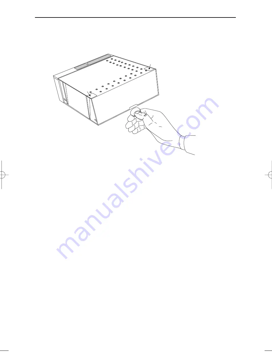
Locate the small hole at the back cover of the scanner. Remove the back
1.
cover by pressing it with a coin as indicated in the figure.
5.
Lead the power supply cable and communication cable through the hole in
the counter.
6.
Plug the communication cable with the 8 pin modular jack into Data port 1 if
the host system features the RS232C or IBM RS485 interface, or into Data
port 2 if the host system features the OCIA or KBW interface. Plug the other
connector of the cable into the appropriate serial port of your POS or com-
puter. Connect the Scantech universal power supply unit to the power supply
port. Lead the cables through the scanner as illustrated in the figure on the
next page.
14
Installing the Pollux P-4010
insert
insert
Pollux_UserM_Deel1.qxd 14-11-2002 09:05 Pagina 14
Summary of Contents for Pollux P-4010
Page 1: ...u s e r s m a n u a l Scantech Pollux P 4010 Bar code laser scanner ...
Page 2: ......
Page 3: ...User s manual Scantech Pollux P 4010 ...
Page 7: ...Chapter 1 The Pollux P 4010 ...
Page 16: ...10 The Pollux P 4010 POS system 12V dc 12V dc 5V dc Pollux P 4010 Scanner control POLLUX ...
Page 17: ...Chapter 2 Installing the Pollux P 4010 ...
Page 23: ...Chapter 3 Mounting options Pollux P 4010 ...
Page 31: ...Appendices A Connector types and pin definitions B Technical Specifications C Troubleshooting ...


