background image

1.2 SCANNING BAR CODES WITH THE POLLUX P-4010

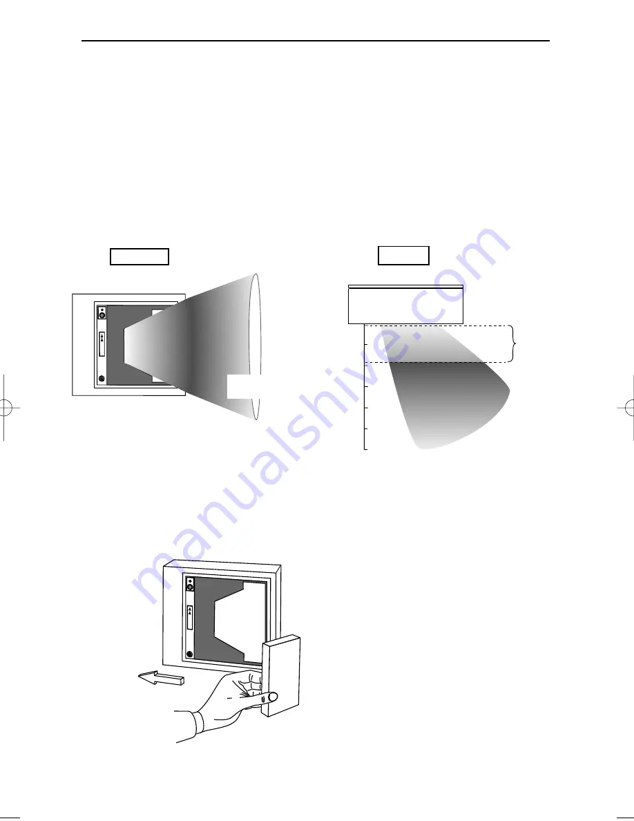
The Pollux P-4010 is an omni-directional scanner featuring a 5 directional scan
field with a 20 lines scan pattern. The scanner's scan volume is illustrated in the
figure below. The optimal reading zone lies between 1 and 9 cm from the scan-
ner window, but bar codes can be read up to 30 cm (11.8 in.) from the scanner
window. The scanner can be used in either fly by or presentation mode.

Scanning a bar code label in fly by mode is very simple: pass the product’s bar
code label along the scanner as illustrated in the figure below.

4

The Pollux P-4010

POLLUX

front view

Fly by mode:

scan pattern 

volume

1 cm

optimal
reading zone

top view

9 cm

30 cm

product flow

scanner in

fly by mode

POLLUX

1. Pass the label along the scanner.

    Bar code is read (green led).


1

sp

ec

ial o

ffe

r

ch

ew

ing

-g

um

Pollux_UserM_Deel1.qxd    14-11-2002    09:05    Pagina  4

Summary of Contents for Pollux P-4010

Page 1: ...u s e r s m a n u a l Scantech Pollux P 4010 Bar code laser scanner ...

Page 2: ......

Page 3: ...User s manual Scantech Pollux P 4010 ...

Page 4: ...es and can radiate radio frequency energy and if not installed and used in accordance with the user s manual may cause harmful interference to radio communications Operation of the equipment in a residential area is likely to cause harmful interference in which case the user will be required to correct the interference at his own expense Any unauthorized changes or modifications to this equipment ...

Page 5: ...ontrolling the scanner from the POS system 9 Chapter 2 Installing the Pollux P 4010 11 2 1 Installing the scanner on a counter surface 13 Chapter 3 Mounting options Pollux P 4010 17 3 1 Flyby mode scanning right to left 19 3 2 Flyby mode scanning left to right 21 3 3 Presentation mode scanning 23 Appendices A Connector types and pin definitions 26 B Technical specifications 28 C Troubleshooting 30...

Page 6: ...logy Evaporated gold on the polygon makes it ultra light giving longer motor life and faster wake up times from the energy saving sleep mode Two versions of the Pollux are available one unit has RS232C and OCIA interfaces and the other has IBM RS485 and Keyboard Wedge interfaces An auxiliary port for connecting another Scantech scanner is standard This manual contains three chapters and three appe...

Page 7: ...Chapter 1 The Pollux P 4010 ...

Page 8: ...nce of physical dam age Refer to the figure on page 6 to locate the interface label and make sure that the scanner interface corresponds with the host system interface Immediately contact your supplier if anything appears to be damaged or if the supported interface does not correspond with the host system interface The various parts of the Pollux P 4010 are 2 The Pollux P 4010 POLLUX LED Sleep mod...

Page 9: ...Guide NOTE The default value for the sleep mode time out is set to 30 minutes When the scanner is in sleep mode the LED is intermittently flashing red LED A red LED indicates that the scanner is ready to read a bar code A green LED indicates a good read Good read speaker The speaker is heard whenever data has been read cor rectly The frequency and volume can be adjusted with the menu labels from t...

Page 10: ... can be read up to 30 cm 11 8 in from the scanner window The scanner can be used in either fly by or presentation mode Scanning a bar code label in fly by mode is very simple pass the product s bar code label along the scanner as illustrated in the figure below 4 The Pollux P 4010 POLLUX front view Fly by mode scan pattern volume 1 cm optimal reading zone top view 9 cm 30 cm product flow scanner i...

Page 11: ... the scanner as illustrated in the figure below The Pollux P 4010 5 POLLUX front view Presentation mode top view 1 cm optimal reading zone 9 cm 30 cm scanner in presentation mode POLLUX special offer chewing gum 1 2 1 Move the label to the scanner Bar code is read green led 2 Move the label from the scanner ...

Page 12: ...The supplier may ask for this number when the scanner needs servicing 6 The Pollux P 4010 POLLUX CAUTION Laser light when open Do not stare into beam IEC825 class 1 laser product Complies with 21CFR1040 as applicable to a class IIa laser product Avoid long term viewing of direct laser light Scantech ID BV Amersfoortsestr 124 3769 AN Soesterberg The Netherlands 12V 12V 5V LISTED ACCESORY 4F10 I T E...

Page 13: ...té IEC 825 1 1993 s appliquant à un produit laser de la classe I Il est également conforme à la U S 21CFR1040 telle qu elle s applique à un produit laser de la classe IIa Eviter de rester exposé longtemps à la lumière directe du laser Danish P 4010 skanneren er i overensstemmelse med sikkerhedsstandarden IEC 825 1 1993 for laserprodukter i klasse I Den er også i overensstemmelse med U S 21CFR1040 ...

Page 14: ...Ia Se debe evitar mirar muy fijo en luz lasérica directa Optical The use of optical instruments with this product will increase eye ha zard Optical instruments include binoculars microscopes and magnifying glas ses but do not include eye glasses worn by the user Radiant Energy The P 4010 uses a low power laser diode operating at 675 nm in an opto mechanical scanner resulting in less than 0 5 mW pe...

Page 15: ...non abrasive glass spray cleaner and a soft lint free cloth 1 5 CONTROLLING THE SCANNER FROM THE POS SYSTEM The Pollux P 4010 can be controlled from the POS system via the RS232C interface Controlling is achieved by transmitting the following single byte com mands to the scanner In the Scantech default setting the following commands are available more details upon request When the scanner is disab...

Page 16: ...10 The Pollux P 4010 POS system 12V dc 12V dc 5V dc Pollux P 4010 Scanner control POLLUX ...

Page 17: ...Chapter 2 Installing the Pollux P 4010 ...

Page 18: ...he scan pattern in a way that suits your application most thanks to the four directional optical assembly For turning the optical assembly please refer to the Pollux Service Manual autho rized personnel only POLLUX Scanner Housing Landscape POLLUX Scanner Housing Portrait Cable supply Cable supply POLLUX PO LLUX 90 180 270 90 180 270 The turning of the optical assembly Note The orientation of the ...

Page 19: ...ical mount to mark the places for the mounting holes at the counter surface and also the hole for the cable supply You can also choose to lead the cables away on the counter surface by removing an insert in the back cover of the scanner Note Use template A for installing the scanner housing landscape Use template B for installing the scanner housing portrait 3 Fasten the vertical mount to the surf...

Page 20: ...in modular jack into Data port 1 if the host system features the RS232C or IBM RS485 interface or into Data port 2 if the host system features the OCIA or KBW interface Plug the other connector of the cable into the appropriate serial port of your POS or com puter Connect the Scantech universal power supply unit to the power supply port Lead the cables through the scanner as illustrated in the fig...

Page 21: ...OWER PORT 2 PORT 1 Interface port 1 Connect the communication cable to this port if the host system features the RS232C or IBM RS 485 interface AUX INTERFACE INTERFACE POWER PORT 2 PORT 1 Interface port 2 Connect the communication cable to this port if the host system features the OCIA or KBW interface ...

Page 22: ...ode labels If you want to change the default settings of the scanner proceed to the Configuration Guide which came with the scanner 16 Installing the Pollux P 4010 AUX INTERFACE INTERFACE POWER PORT 2 PORT 1 SCANNER FRONT To activate Data port 2 OCIA or KBW interface follow this sequence 1 Plug in the appropriate interface cable and then power up the scanner 2 Scan the following codes from the Con...

Page 23: ...Chapter 3 Mounting options Pollux P 4010 ...

Page 24: ...rized personnel only The Pollux P 4010 can be installed fixed on a counter surface or sunk into the counter surface Your choice depends on the way you intend to use the scanner The following pages illustrate which mounting options are available To install the Pollux in flyby mode for scanning from Right to Left please refer to Section 3 1 To install the Pollux in flyby mode for scanning from Left ...

Page 25: ...surface Product flow special offer chewing gum 3 1 FLYBY MODE SCANNING RIGHT TO LEFT To scan from Right to Left install the scanner housing by a landscape orientation or b portrait orientation a Scanning from Right to Left scanner housing landscape orientation 3 1a1 ...

Page 26: ...canner housing portrait orientation POLLUX Cable supply On counter surface special offer chewing gum Cable supply Sunk into counter surface POLLUX Product flow special offer chewing gum Not recommended The need to lift the products being scanned increases 3 1b1 3 1b2 ...

Page 27: ...RIGHT To scan from Left to Right install the scanner housing by a landscape orientation or b portrait orientation a Scanning from Left to Right scanner housing landscape orientation POLLUX Cable supply On counter surface Product flow spec ial offer chew ing g um 3 2a1 ...

Page 28: ...ner housing portrait orientation spec ial offer chew ing g um Cable supply On counter surface POLLUX POLLUX Cable supply Sunk into counter surface Product flow spec ial offer chew ing g um Not recommended The need to lift the products being scanned increases 3 2b1 3 2b2 ...

Page 29: ...ode install the scanner housing by a landscape orientation or b portrait orientation a Scanning in presentation mode scanner housing landscape orienta tion POLLUX Cable supply On counter surface special offer chewing gum 1 2 Product flow Not recommended Due to a minimized scan pattern 3 3a1 ...

Page 30: ...scanner housing portrait orientation Cable supply Sunk into counter surface POLLUX special offer chewing gum 1 2 Product flow Cable supply POLLUX On counter surface special offer chewing gum 1 2 Product flow Not recommended Due to a minimized scan pattern 3 3b1 3 3b2 ...

Page 31: ...Appendices A Connector types and pin definitions B Technical Specifications C Troubleshooting ...

Page 32: ... 6 7 10 A CONNECTOR TYPES AND PIN DEFINITIONS There are two dual interface versions of the Pollux available RS232C OCIA and IBM RS485 Keyboard Wedge The various pin definitions for the applicable Data port are given on page 31 The connector to be used for the port is indicated below To activate Data port 2 OCIA or KBW interface follow this sequence 1 Plug in the appropriate interface cable and the...

Page 33: ...A interface Data port 2 Description Not Con IO A IO B Not Con GND Not Con Direction input output input output Reserved IBM RS485 interface Data port 1 Pin 1 2 3 4 5 6 7 8 Pin 1 2 3 4 5 6 7 8 Description IFID1 KB_DATA KB_CLCK PC_DATA PC_GND PC_CLCK PC_5V IFID2 Direction input output output input input input input KBW interface Data port 2 Pin 1 2 3 4 5 6 7 8 Pin definition for dual interface versio...

Page 34: ...Interface port 2 OCIA or KBW Auxiliary port Secondary scanner 250 mA max Optical Light source Visible laser diode 650 nm Depth of field 300 mm Scan pattern 5 directions scan field 20 lines scan pattern Scan rate 2000 scans second Decoding Bar code types EAN UPC JAN Add on Code 128 EAN 128 Code 39 Code 32 Codabar ITF Physical Weight 1 2 kg Dimensions L x W x D 183 x 210 x 70 mm 7 2 x 8 25 x 2 75 in...

Page 35: ...edition UL1950 third edition c UL according CSA22 2 950 95 Flammability rate 94V 0 EM Compatibility Radio and TV interference EN 55022 Class B 1994 FCC part 15 Class A 1992 Harmonic current emissions EN 61000 3 2 1995 EM immunity EN 50082 1 1992 based on ElectroStatic Discharge ESD IEC 801 2 1991 Radio frequency immunity IEC 801 3 1984 ENV 50140 1993 Electrical fast transient IEC 801 4 1988 ...

Page 36: ...problems you may encounter when using the scanner If troubles occur take a moment to read the information in this section However before referring to the diagnostic tips make sure that the scanner is installed as described in Chapter 2 and that all cables are properly connected ...

Page 37: ... handshaking with the host system Switch the host system on and check connection and communication settings The laser is not functioning The laser is defect Contact your supplier The ambient temperature is too high Make sure the scanner has enough air ventilation and is not placed in direct sunlight The scanner is on but a bar code cannot be read The LED is red Diagnostic Tips The scanner is in Sl...

Page 38: ...are connected and your host system is ready to receive data The communication cable is not connected to the serial port of your host system Refer to the manual of your host system to locate the serial port The communication settings of the host and scanner do not match Ensure that the setting value for both devices are the same For proper adjustment values see the Configuration Guide The communica...

Page 39: ...R FRONT SCANNER FRONT TEMPLATE A SCANNER HOUSING LANDSCAPE TEMPLATE B SCANNER HOUSING PORTRAIT Hole in counter surface for cable supply Hole in counter surface for cable supply Scanner outline Scanner outline ...

Page 40: ...Scantech ID BV Amersfoortsestraat 124 3769 AN Soesterberg The Netherlands Phone 31 0 33 469 84 00 Fax 31 0 33 465 06 15 E mail info scantech id com Internet www scantech id com ...

Reviews: