11
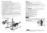
Automatic drain Cord
Automatic drain Valve
Automatic drain Cord Connector
End
"A"
End
"B"
Plumb to Drain
Line in accordance
with Code
Arrow indicates
correct direction
of flow
Drain Valve
Nipple
Plumb to
Drain Line
Automatic
drain
Valve
Plumbing to be performed by a qualified licensed
plumber and shall be in accordance with applicable
national and Local Codes. Unit drains by gravity.
A drain line that is lower than Automatic drain
assembly must be available. The Automatic drain
valve outlet is threaded 15mm. Check plumbing
code for receptor, trap and vent requirements.
Use copper or brass nipple 15mm x
90mm
or
longer (not supplied) to connect the Automatic
drain valve (end "B") to the Drain Valve (valve end
"A" & "B" are indicated on bottom of Automatic
drain Valve).
DO NOT REMOVE THE DRAIN VALVE.
Removal may cause equipment and property
damage. If there is not enough room for the valve,
an elbow and a short nipple (not provided) can
be added.
Installation Instructions
1. Disconnect all power supplied to the unit.
2.
3.
4. Open Drain Valve (handle must be aligned with
brass nipple as shown).
5. Connect the Automatic drain cord connector to the
two pin connector as shown.
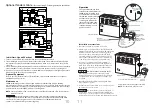
Operation
The optional Automatic drain
feature automatically drains the
SAWO system following each
use. the stainless steel tank is
flushed and remains empty
until the steam generator
is used again. A time delay
(about 2 hours) allows the
water to cool down before
it drains resulting in a safe
gentle operation.
Drain Valve
(shown in the correct open position)
DO NOT REMOVE THIS DRAIN VALVE
Steam Generator
Nipple
(copper or
brass nipple
15mm x
90mm
or longer
(not supplied))
DO NOT TURN OR REMOVE THE DRAIN VALVE
Steam Generator
Automatic drain shown fully assembled
NOTE:
For illustrative purposes only.
Do not drain into a steam enclosure or
any location where accidental contact with drain
water may occur. In the event of a power failure, the
Automatic drain valve will open and discharge hot water.
!
WARNING
!
CAUTION
(2) Pin Connector
for Automatic
drain
Optional Tandem Cable
-
for connecting 2-5 steam generators in tandem
1. Turn on control. Follow specific instruction sheet provided with controls.
2. Steam will begin to appear in 5 minutes at the steam head. Steam will shut off when desired
temperature is reached and will automatically resume when room temperature drops below
set point.
3. Steam will shut off automaticaly when control counts down to zero. to shut steam off manually,
turn control OFF. To clear steam from enclosure area, turn shower on before opening door.
4. If unit does not start and control does not turn ON (control display does not light up) then turn
breaker off for twenty seconds and try again.
Refer to specific instruction sheets for installation, operation and maintenance of optional
equipment and accessories.
SAWO steambath generators require little maintenance. Other than periodic draining,
maintenance procedures are minimal. Every 2 months, or more often in "hard" water areas, the
manual drain valve should be opened fully flushing out accumulated materials, salts and other
particles which are naturally by-products of boiling water.
NOTE:
Flush a minimum of two hours after the control has been turned off to insure that the
water has cooled.
Draining immediately after a steam cycle may expose PVC and other piping
to high temperature water. Check local requirements. The unit will refill automatically when
the control is activated again. In areas of very hard water, a SAWO automatic drain
system is recommended for generator longevity.
Optional Equipment
Initial Start-Up and Checkout
Maintenance
10
!
WARNING
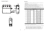
SECOND UNIT
MASTER UNIT
TO THIRD UNIT
TO FOURTH UNIT
TO FIFTH UNIT
C
C
FUSE
GROUND
CONTACTOR
WATER
FEED
SOLENOID
VALVE
RELAY 1
CONTROL
BOARD
CONTROL
TEMP
SENSOR
AUTO
DRAIN
TO
PROBE
TRANSFORMER
L N
G
HEATING
ELEMENT
S
C
C
FUSE
GROUND
CONTACTOR
WATER
FEED
SOLENOID
VALVE
RELAY 1
CONTROL
BOARD
CONTROL
TEMP
SENSOR
AUTO
DRAIN
TO
PROBE
TRANSFORMER
L N
G
HEATING
ELEMENT
S
STS
230V 1N~
kW
KATSO OHJEIST
A
BEACHTEN SIE DIE
ZUSÄTZLICHEN
WICHTIGEN
ANWEISUNGEN IN DER
BEDIENUNGSANLEITUNG
READ THE
MANUAL
FOR
ADDITIONAL
IMPOR
TANT
INSTRUCTIONS
LÄGG MÄRKE
TILL DE
VIKTIGA


