1
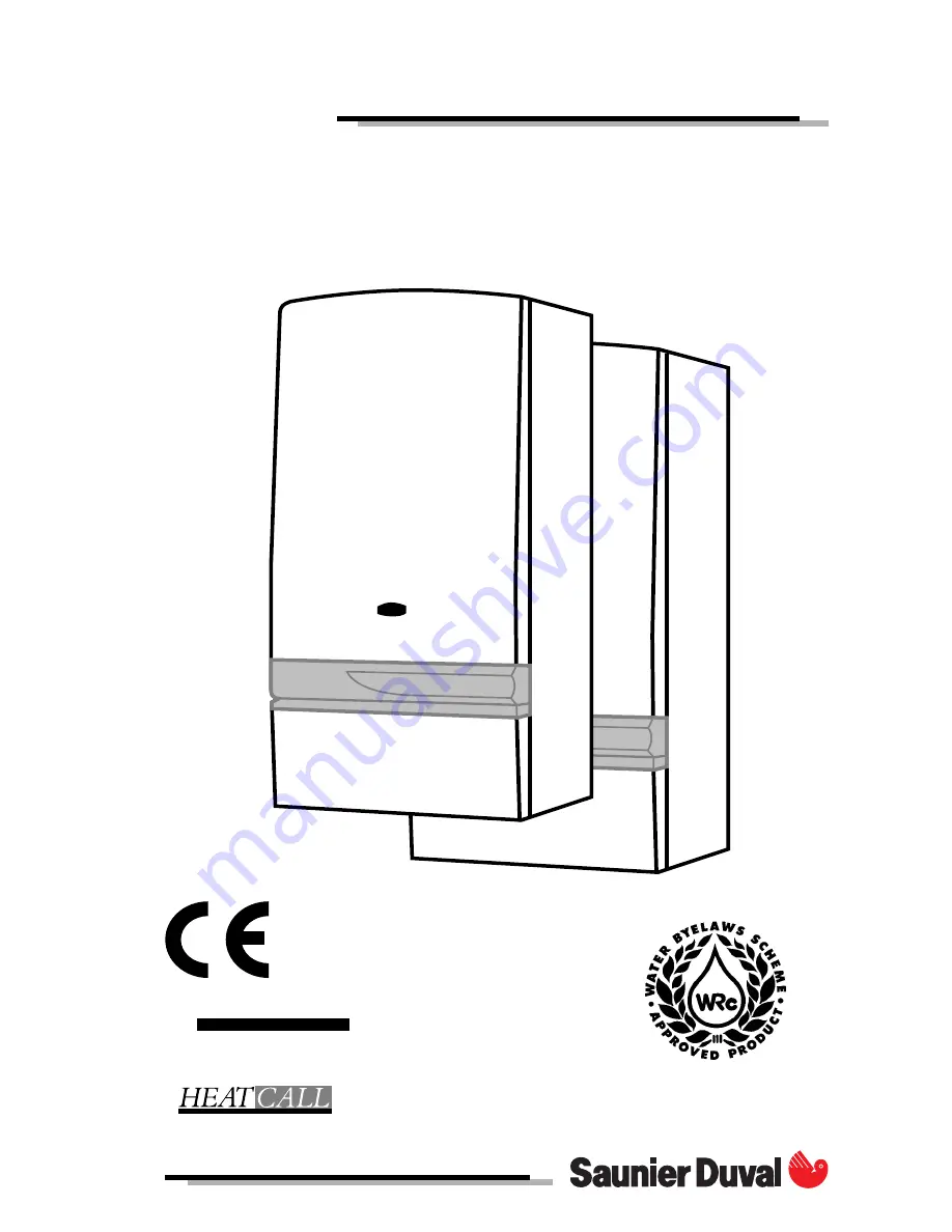
THELIA
THIS IS A CAT II2H3+ APPLIANCE
01773 828100
I N W A R R A N T Y
T E C H N I C A L H E L P L I N E
01773 828400
Page 1: ...1 THELIA THIS IS A CAT II2H3 APPLIANCE 01773 828100 IN WARRANTY TECHNICAL HELPLINE 01773 828400...
Page 2: ...marked on the label attached to the inside of the door Refer to the Introduction section page 3 for a description of the basic functions of the boiler The Users section describes how to safely operate...
Page 3: ...2H3 Gas Category for use with natural gas G20 as distributed in the United Kingdom or with butane or propane gas G30 31 These instructions should be carefully followed for the safe and economical use...
Page 4: ...043a Hab 130 Note On pressing the ON button the fan will be heard to run at full speed after which the ignition sequence will start and the pilot will light Should the pilot fail to remain alight or g...
Page 5: ...33 Diag 7 HEATING HOT WATER Place the selector lever diagram 4 to position winter In this position the domestic hot water will have PRIORITY HEATING ONLY Turn the selector switch diagram 8 to position...
Page 6: ...four hour format for example 1300 for 1pm see diagram 12 Helpful Hint The and buttons are used to change times Press and release for small changes If you press and hold down the time will run To Set...
Page 7: ...ton again The display will now show the first Off time you have just entered Repeattheabovefortheremaining On and Off times When you have set the On and Off times you require place the slide switch to...
Page 8: ...during a holiday After the programmed time has gone by the boiler returns to its normal programmes To set the Hold or Holiday feature carry on as follows Place the slide switch to Timer the letter h w...
Page 9: ...boiler The valve MUST NOT BE TOUCHED except by a competent person If the valve discharges at any time switch the boiler off and isolate it from the electrical supply Contact your installation servic i...
Page 10: ...e in sanitary hot water mode l min 3 3 Specific flow rate for 30 C temperature rise l min 11 11 Mini supply pressure bar 0 3 0 3 Max supply pressure bar 10 10 Electrical supply V 230 230 230 Amperage...
Page 11: ...pen open 1 turn open 3 turns open 2 turns Pressure loss between flow and return boiler connections metres head Heat output kW 8 9 10 11 12 13 14 15 16 17 18 19 20 21 22 23 3 Btu h 30387 34142 37557 40...
Page 12: ...ver 8 Expansion vessel 9 Pump 10 Automatic air vent 11 Burner 12 Heat exchanger air vent 13 Heat exchanger 14 Multi functional control 15 Safety electrovalve THELIA 23 E only 16 Hight limit thermostat...
Page 13: ...23 Airflow switch A Heating return C Heating flow F Gas inlet 1 ON push button 2 OFF push button 3 Spark generator 4 Central heating water temperature adjustment 5 Temperature gauge 6 Pressure gauge 8...
Page 14: ...5a A Heating return with isolating valve m B Cold water inlet with isolating valve p C Heating flow with isolating valve q drain screw r and safety valve s D Domestic hot water out E Electrical connec...
Page 15: ...e with any type of installation Heating surfaces may consist of radiators convectors or fan assisted convectors Caution if the materials used are of different types corrosion phenomena may develop In...
Page 16: ...emplate on wall in required position mak ing allowance for the necessary clearances etc Mark the position of the holes for the hook and the connecting plate Drill plug and fix the connecting plate and...
Page 17: ...t window 400 F from an adjacent air vent 600 G from vertical or horizontal air pipes 600 H from an external corner of the building 300 I from an internal corner of the building 1000 L from the ground...
Page 18: ...e installation of this boiler must be carried out by a competent person in accordance with the relevant requirements of the current issue of The Gas Safety Installation and Use Regulations The Buildin...
Page 19: ...29 E F D C B A 234 50 mini 29 60 255 mini Diagram 30 Cutting the flue hole Making allowance for the slope of the flue cut the hole in the external wall preferably using a 115 mm diameter core drill I...
Page 20: ...redu ced in this way it will be necessary to drill two fixing holes in these pipes to match the fixing holes in the aluminium connector The PVC connector is used to connect the PVC extension pipe to...
Page 21: ...m 41 Important the gas connection must be made first as there is no flexibility in this connection Do not forget the sealing washer Connect the aluminium pipe onto the central outlet of either the str...
Page 22: ...plate to leave fan outlet pointing upward Using the alternative set of three holes in the mounting plate fasten the fan to the mounting plate see diagram 45 Disconnect air pressure switch tube from re...
Page 23: ...d see diagram 41 Important The gas connection must be made first as there is no flexibility in this connection Do not forget the sealing washer Fit the internal plastic flange Q Push it along the pipe...
Page 24: ...any of the terminals of this plug All models In case of difficulty obtaining a suitable timeclock room thermostat a programmable room thermo stat is available as an accessory Saunier Duval part number...
Page 25: ...plug Voltage free room thermostat Do not connect Voltage free room thermostat Do not connect Voltage free cylinder thermostat External controls plug Time clock External controls plug Timeclock room th...
Page 26: ...Filling the system With the selector diagram 51 or 52 in the winter position or open the shut off valves q m and p diagram 53 the slot of the screw corres ponds to flow direction the bleed plug situat...
Page 27: ...he left hand position Gas pressures The main burner pressure should be checked dur ing commissioning to make sure the correct in put is obtained Proceed as follows Shut down boiler Remove screw from t...
Page 28: ...ure shown on the pressure gauge diag 58 is less than 1 bar the system must be filled up immediately Call the nearest after sales service department Air in the heating system Persistent air in the heat...
Page 29: ...run when the burner is lit and will continue to run after burner extinction This can be useful on certain installa tions that requireconstant heating water circula tion To change the pump operation t...
Page 30: ...30...
Page 31: ...31...
Page 32: ...32 Le Technipole 8 av Pablo Picasso 94132 Fontenay sous Bois cedex T l phone 1 49 74 11 11 T lex 262 958 T l copie 1 49 74 11 01 102740 D 08 96...