background image

12

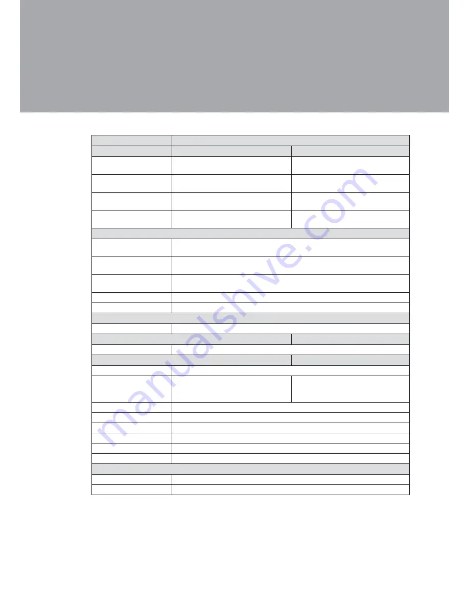
Specification

5. 

Model Name

Saturn AIO (8” and 12”)

Motherboard

N270

D525

Processor

Intel® AtomTM processors N270 

1.6Ghz L2 512K FSB 533MHz

Intel Pineview D525, dual core  

1.8Ghz, L2 1M  

Chipset

Intel® 945GSE Express c 

ICH7M

CPU integrated g ICH

System Memory

1 X DDR2 DIMM up to 2GB FSB 

533MHz

1 x DDR3 DIMM socket up to 4GB, 

FSB  800Mhz

Graphic Memory

Intel® GMA 950 share system mem-

ory up to 224MB

Intel GMA 3150 share system 

memory up to 384MB

LCD Panel

LCD Size

8.4” TFT LCD

12.1” TFT LCD

Brightness

8.4” : 200~250 cd/m²

12.1” : 400~500 cd/m²

Maximum Resolution

8.4”: 800x600

12.1”: 1024x768

Touch Screen

Resistive

Tile Angle

0

o

~ 60

 o

Storage Device

Hard Drive

1x2.5” SATA HDD or SSD

Expansion

mini-PCI express slot

1

Rear I/O

USB Port

4 (USB 2.0)

Serial / COM

4 x RJ45  (COM1/COM2 standard 

COM,  COM3/COM4 pin 9  

+5V/+12V power by jumper )

4 x RJ45 (COM1/COM2 standard 

COM., COM3 /COM4 pin9 power by 

BIOS setting )

LAN Port

1 x RJ-45 (10/100/1000Mbps Giga LAN)

Second Display

1 (DB-15 Female)

Cash Drawer Port

1 x RJ-11 (12V / 24V)

DC Jack

1 (DC 19V)

Power button

1

Power

Adapter (65W, 19V, 3.4A)

Peripherals

MSR

Standard integrated 3 Track MSR (PS/2 Standard, optional USB)

Finger print

Optical Finger Printer Reader (USB, optional)

Summary of Contents for AIO 8"

Page 1: ...USER MANUAL VERSION 1 2 April 2013 Saturn AIO 8 and 12...

Page 2: ...l or consequential damages in connection with the furnishing performance or use of this material This document contains proprietary information that is protected by copyright All rights are reserved N...

Page 3: ...ct should never be placed near or over a radiator or heat register or in a built in installation unless proper ventilation is provided This product should be operated from the type of power indicated...

Page 4: ...its working life Instead the device should be taken to the waste collection centers for activation of the treatment collection recycling and disposal procedure To prevent possible harm to the environ...

Page 5: ...evision History Changes to the original user manual are listed below Revision Description Date 1 0 Initial release December 2009 1 1 12 1 LCD brightness updated November 2011 1 2 C46 MB added April 20...

Page 6: ...r View 3 2 4 I O view 4 2 5 Dimensions 5 2 5 1 8 4 System 5 2 5 2 12 1 System 5 3 System Assembly 6 3 1 RAM Module Replacement 6 3 2 HDD Replacement 7 3 2 1 HDD replacement for 8 4 system 7 3 2 2 HDD...

Page 7: ...N270 Motherboard 14 6 1 1 Motherboard Layout 14 6 1 2 Connectors Funcions 15 6 1 3 Connectors Funcions 16 6 2 D525 Motherboard 21 6 2 1 Motherboard Layout 21 6 2 2 Connectors Functions 22 6 2 3 Jumpe...

Page 8: ...ing List 1 Standard Accessories 1 1 Optional Accessories 1 2 System a Driver bank b Power adapter c Power cord d RJ45 DB9 cable x2 e a b c Stand a WLAN Card internal antenna b Fingerprint reader c a b...

Page 9: ...2 System View 2 Front View 2 1 Metal Stand 1 Touch Screen 2 Built in MSR 3 With Stand Without Stand Side View 2 2 1 4 2 3 Ventilation holes 4...

Page 10: ...3 Rear View 2 3 VESA Mounting Holes 5 Ventilation 6 HDD Door 12 1 7 8 4 System 5 6 COM4 19V IN COM3 COM2 COM1 CD PS 2 12 1 System 7 5...

Page 11: ...00 d COM Port 1 2 3 4 from left to right e VGA f DC jack g Power button h PS 2 i Line out j Power LED indicator Note The location of the I O ports may vary slightly depending on whether you have a sys...

Page 12: ...5 Dimensions 2 5 251 6 192 50 183 5 194 2 30 5 50 58 326 247 193 2 237 2 31 4 50 8 4 System 2 5 1 12 1 System 2 5 2...

Page 13: ...e screws x8 to access the motherboard See Chapter 3 2 Use both fingers to pull the ejector 2 clips out of the sides of the module Slide out to remove the memory 3 module from the memory slot Installin...

Page 14: ...g bracket from the motherboard HDD replacement for 8 4 system 3 2 1 The HDD is installed on the motherboard you need to uncover the rear cover rst to access it If your system is equipped with a stand...

Page 15: ...nnector on the I O panel HDD replacement for 12 1 system 3 2 2 You can access the HDD easily by turning the system to the rear side on a 12 system Please see detailed procedure below Power Adapter Ins...

Page 16: ...9 Peripheral Installation 4 Stand Installation 4 1 Fasten the screws x4 The 1 screw location may slightly differ according to the system size 8 4 and 12 1 being installed...

Page 17: ...bit1 6 GND Cash Drawer Controller Register The Cash Drawer Controller use one I O address to control the Cash Drawer Register Location 48Ch Attribute Read Write Size 8bit BIT BIT7 BIT6 BIT5 BIT4 BIT3...

Page 18: ...Bit 1 Reserved Bit 0 Reserved Note Please follow the Cash Drawer control signal design to control the Cash Drawer Cash Drawer Control Command Example Use Debug EXE program under DOS or Windows98 Comma...

Page 19: ...Brightness 8 4 200 250 cd m 12 1 400 500 cd m Maximum Resolution 8 4 800x600 12 1 1024x768 Touch Screen Resistive Tile Angle 0o 60 o Storage Device Hard Drive 1x2 5 SATA HDD or SSD Expansion mini PCI...

Page 20: ...ater Proof IP54 for front bezel Communication Wireless LAN mini PCI E wireless LAN card 802 11 b g or n Dimension W x D x H 8 4 251 5 x 180 x 193mm 12 1 326 x 210 5 x 202mm Weight N W G W 8 4 2 5kgs 3...

Page 21: ...14 Jumper Setting 6 N270 Motherboard 6 1 Motherboard Layout 6 1 1...

Page 22: ...Connector CN22 5 Wire Touch CN24 FT Status Interface DDR2_A1 DDR2 SO DIMM PWR3 19V Power Adaptor RJ11_3 Cash Drawer Connector RJ45_3 LAN On Board RJ45_4 COM1 4 FAN_SYS3 System FAN Connector MINI_PCIE...

Page 23: ...Setting Function JP8 COM3 Pin10 RI 5 7 9 11 2 1 3 6 8 10 12 4 5V 11 12 8 10 5 7 9 2 1 3 6 4 12V 11 12 8 10 5 7 9 2 1 3 6 4 COM4 Pin10 RI 11 12 8 10 5 7 9 2 1 3 6 4 5V 11 12 8 10 5 7 9 2 1 3 6 4 12V 11...

Page 24: ...on JP4 12V 2 1 3 4 19V 2 1 3 4 Power Mode Setting Function JP5 ATX Power 2 1 AT Power 2 1 CMOS Operation Mode Function JP6 CMOS Normal 2 1 CMOS Reset 2 1 VGA Power Setting Function JP9 No Power 2 1 12...

Page 25: ...3 6 4 6 1280 x 1024 24 Dual LVDS 8 5 7 2 1 3 6 4 7 800 x 600 24 Single LVDS 8 5 7 2 1 3 6 4 9 1024 x 768 18 Single LVDS 8 5 7 2 1 3 6 4 11 800 x 600 18 Single LVDS 8 5 7 2 1 3 6 4 12 800 x 600 18 Sing...

Page 26: ...6 2 1 RJ11_3 USB3 USB4 RJ45_3 CN3 CN6 CN4 SATA2 CN5 SATA1 SATA3 RJ45_4 CN7 CN8 CN9 MINI_PCIE1 CN12 CN20 VGA3 CN17 CN11 CN13 PWR3 PWR4 CN21 CN22 SW3 DDR3_A1 CN23 CN18 CN15 CN16 CN10 CN14 CN19 CN24 CN25...

Page 27: ...Internal DC Jack CN22 Power On Switch Connector CN23 TCOM Power CN24 LVDS 18bit CN25 Battery Connector PWR3 DC Jack RJ11_3 Cash Drawer RJ45_4 COM1 4 RJ45_5 LAN SATA2 SATA SATA3 SATA SKT3 BIOS USB3 US...

Page 28: ...ATX Power AT Power 2 1 2 1 3 4 2 1 3 4 2 1 Manufacturer Default Setting 2 1 open 2 1 short Jumper Setting 6 2 3 System Reset Function JP7 System Normal System Reset CRT Power Ctrl Function JP8 HW BIOS...

Page 29: ...from CMOS Reset to CMOS normal 6 Connect the power cable and power on the system CMOS Operation Mode Function JP5 CMOS Normal CMOS Reset 2 1 2 1 LCD ID Setting Several con gurations are applied to di...

Page 30: ...Function JP9 COM3 5V 8 5 7 2 1 3 6 4 COM3 12V COM4 5V 8 5 7 2 1 3 6 4 COM4 12V Please see the following page for jumper JP9 location 8 5 7 2 1 3 6 4 8 5 7 2 1 3 6 4 BIOS Utility setup Power on the sys...

Page 31: ...stem and press 1 the DEL key when the system is booting up to enter the BIOS Setup utility Select the Advanced tab 2 Select Power Con guration 3 COM VGA Ports and press Enter to go to display the avai...

Page 32: ...u can nd every individual driver and utility that enables you to install the drivers on the system Please insert the Driver CD into the drive and double click on the index htm to select the models You...

Reviews: