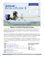


IntelliFlow 3 Liquid Installation Guide
6
875-3000-100 Rev A1
INSTALLING INTELLIFLOW 3
Controller Installation
Mount the controller in an available space on the aircraft, for example, in or around the baggage compartment. Ensure
there is enough space for making connections and cable bend radius. Access is needed behind the mounting surface to
attach the nuts to the bolts (part P). When you have selected the mounting location, use one of the plate stencils (part S or
part T) as a template to mark fastener positions. Use drill bit sizes 16 or 28 to drill holes for the fasteners and secure the IF3
Controller (part I) to the aircraft using hardware (part P).
Rack Mounting:
It is recommended to use the
Mounting Layout Template (PN 601-1313-000) to
assure accuracy for locating the correct position of
the vibration isolators.
This template is available for
purchase
.
Horizontal Mounting:
It is recommended to use the Mounting
Layout Template (PN 601-1317-000, Part T) to assure accuracy
for locating the correct position of the vibration isolators.
This
template is available for purchase
.
1. CPU Rack Mounted Upright (PN 601-1313-000, Part S)
a) Vibration
Isolators (Part Pc)
With Template (Part S)
i) Place the template (Part S) in the desired location while heeding the above recommendations.
ii) Use the template to mark the fastener hole locations of the four vibration isolator feet (Part Pc). There
are eight holes at #28 drill bit (0.140”).
iii) Drill holes being careful not to cause damage.
iv) Use parts Pd, Pe, and Pf to attach Pc to the airframe.
v) Use parts Pa and Pb to attach the CPU rack system to vibration
isolators (Part Pc)
.
b) Vibration Isolators Without Template
i) Using parts Pa and Pb attach vibration
isolators (Part Pc)
to the CPU rack system.
ii) Place CPU in the desired location while heeding the above recommendations.
iii) Mark airframe fastener locations using the open holes in the vibration
isolator
feet.
iv) Drill holes being careful not to cause damage.There are eight holes at #28 drill bit (0.140”).
v) Use parts Pd, Pe, and Pf to attach vibration isolators (Part Pc) to approved structure.
2. CPU Horizontally Mounted With Vibration
Isolators
a) Horizontal Mounts With Template (PN 601-1317-000, Part T)
i) Place the template (Part T) in the desired location while heeding the above recommendations.
ii) Use the template to mark the fastener hole locations of the four vibration
isolator
feet (Part Pc). There
are eight holes at #28 drill bit (0.140”).
iii) Drill holes being careful not to cause damage.
iv) Use hardware from the pre-assembled rack mount system to attach horizontal mounting brackets
(Part O) to the CPU.
v) Use parts Pd, Pe, and Pf to attach vibration isolators (Part Pc) to approved structure.
vi) Use parts Pa and Pb to attach vibration mounts to horizontal mounting brackets (Part O).