IntelliFlow 3 Liquid Installation Guide
3
875-3000-100 Rev A1
SAFETY INFORMATION
Read and Follow Safety Messages
• In these instructions, you may see the heading and/or the safety alert symbol . They indicate
a hazardous situation that, if not avoided, could result in death or serious injury. The safety messages provide
information to identify a hazard associated with potential injury.
• Read and understand this manual and all the warnings below before installing, operating, or performing maintenance
or service. FAILURE TO DO SO MAY CAUSE IRREVERSIBLE DAMAGE TO YOUR SYSTEM.
• Keep this manual and all related safety information with the manuals for your aircraft.
Plan your installation by considering the following:
• Cable lengths
• Clearance space
• Power source
• Aircraft structure
• Visibility
Consider using existing hardware and hardware locations. Avoid drilling holes that may damage other
equipment (such as structural frame members, electrical cables, or fluid lines).
Do not obstruct the view of, or access to, other instruments or the flying visibility of the operator.
Do not allow anyone to operate without instruction.
For trouble-free operation and maintenance of your IF3 system, adhere to the following
recommendations.
• Avoid using IF3 in extreme environmental conditions (40-140°F is recommended operating
temperature range).
• Wash the hopper/boom system thoroughly and methodically after spray sessions to avoid
gumming up the flow meter unit.
TABLE OF CONTENTS
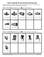
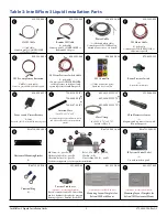
Parts Covered by this Installation Guide
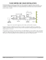
Flow Meter and Valve Installation
Coypright Notice
Satloc, a company of Texas Transland, LLC
Copyright Satloc © (2021). All rights reserved.
No part of this manual may be reproduced, transmitted, transcribed, stored in a retrieval system or translated into any language or computer language, in any form
or by any means, electronic, mechanical, magnetic, optical, chemical, manual or otherwise, without the prior written permission of Satloc.
Latest Version of the IntelliFlow 3 Liquid Installation Guide
Satloc is dedicated to providing updated versions of installation guidebooks for its customers. Scan
the QR code to verify you have the latest version of the IntelliFlow 3 Liquid Installation Guide or
click this link to make sure this is the latest version _____________.


