Chapter 2 Installation
Electrical Installation
8
ETC ONE PLUS Network Communicator
Electrical Installation
The equipment installation shall conform to the following
instructions:
a) a switch or circuit-breaker shall be included in the building
installation;
b) It shall be in close proximity to the equipment and within easy
reach of the OPERATOR;
c) It shall be marked as the disconnecting device for the
equipment.
Before installing, ensure that all incoming power sources are
shut OFF. Failure to observe this practice can result in serious
or even fatal injury and damage to equipment.
Power Source Connection
Before connecting your device to the power source, check the label on the the
device to ensure that it is equipped with the appropriate power supply.
AC power supply: Connect the line wire to terminal L/+ and the neutral wire to
terminal N/-.
DC power supply: Connect the positive wire to terminal L/+ and the negative
wire to terminal N/-.
Figure 2-5 Power Source Connection
Communication Port Connection
Before installing the Communication Module, ensure that all
incoming power sources are shut OFF. Failure to observe this
practice can result in serious or even fatal injury and damage to
equipment.
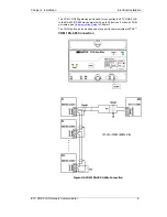
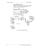
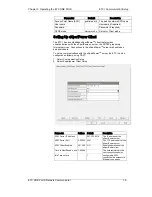
Two communication ports are available on the ETC I:
COM1 (master): RS-485, devices side
COM2 (slave): network side
Ethernet 10/100BaseT
CELLULAR
–
2G/3G
RS-232 or RS-422/485


