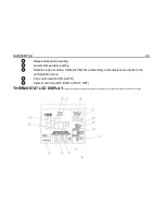
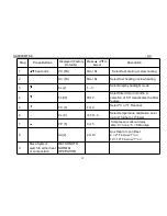
Saswell SAS900MTK-0 Operating Instructions Manual Download Page 19

SAS900MTK-0

A0

18

No Cool

1. System Switch not set to Cool
2. Loose Connection to thermostat

or System

3. Compressor lock-out is activated.

Set system switch to Cool and lower set point
below room temperature.
Verify thermostat and system wires are
securely attached.
Wait five minutes until the compressor
protection time is up. There may be up to a five
minute delay before the thermostat can
activate the compressor if the compressor
lock-out option is selected in the configuration
menu.

WARRANTY POLICY--------------------------------------------------------------------------------------------------------------

Warrants the following:
Only cataloged products sold to distributors are warranted to the original purchaser, and to be free from
defects in material and workmanship, for a period of one (1) year from the date of purchase, unless
specified in writing for a different period.

Prior to returning this product to us, the purchaser shall give us

notice in writing stating how this product fails to fulfill this warranty. No product shall be accepted for repair
or replacement without a required written notice and without prior written authorization and shipping
address having been received by the purchaser . Only our factory is authorized to perform services under
this warranty. Transportation charges are to be prepaid by the purchaser.
This warranty does not extend to any product that has been subjected to misuse, abuse, neglect, accidents,
alternations, improper installation or use in violation of the printed instructions furnished by us. This
warranty neither applies to batteries not deterioration of, nor damage to the product caused by the use of
faulty batteries.

Summary of Contents for SAS900MTK-0

Page 1: ...SAS900MTK 0 A0 1 OPERATING INSTRUCTION SAS900MTK 0...

Page 2: ...acy 1 F or 0 5 C Dimensions 5 1 W X 3 7 H X 1 2 D Color White FEATURES Large LCD display with backlight continuous backlight option Simultaneous heat and cool set point storage Display of room tempera...

Page 3: ...g and electrical codes and ordinances Do not short jumper across terminals on the gas valve or at the system control to test installation This will damage the thermostat and void the warranty Do not s...

Page 4: ...eating and cooling system by removing the fuse or switching the appropriate circuit breaker off 3 Remove the cover of the old thermostat This should expose the wires 4 Label the existing wires from th...

Page 5: ...re setting 2 Lowers temperature setting 3 Selects clock set mode Indicates filter time remaining and selects menu items in the configuration menu 4 Fan control switch ON AUTO 5 System control switch C...

Page 6: ...e thermostat activates auxiliary heating 11 Battery Icon If the Battery Icon is flashing batteries need to be replaced 12 Indicates the thermostat is calling for HEAT or COOL 13 Indicates the current...

Page 7: ...y removing the fuse or switching the appropriate circuit breaker to the OFF position before removing the existing thermostat 1 Turn off power to the heating and cooling system by removing the fuse or...

Page 8: ...ching wire terminals See Wiring Diagrams Section 3 Figure 3 CAUTION Be sure exposed portions of wires do not touch other wires 10 Tighten screws on terminal block Gently tug on each wire to be sure of...

Page 9: ...ystem is an electric heat that REQUIRES the thermostat to turn on the fan on a call for heat place do not cut Jumper1 If your system does not require the thermostat to energize the fan on a call for h...

Page 10: ...e blower should stop immediately HEATING SYSTEM 1 Move the SYSTEM switch to the HEAT position If the auxiliary heating system has a standing pilot be sure to light it 2 Press to adjust thermostat sett...

Page 11: ...tat is installed correctly REPLACING BATTERIES If your thermostat was pre installed the batteries may be in place If the battery icon on the display is flashing it indicates that the batteries need to...

Page 12: ...F position then press and hold the and buttons in a same time for 5 seconds to enter the configuration menu The display will show the first item in the configuration menu Press the button to move to t...

Page 13: ...acklight mode 4 FL 00 00 12 Select filter time in months A selection of 00 deactivates the filter feature 5 FC F F or C Select C or F Readout 6 CL 0 4 TO 4 Select temperature calibration point up to 4...

Page 14: ...duce very accurate temperature control and can be set to your personal preference FA cycles the heat pump system at a 0 5 F differential and Aux heating at 2 0 F below first stage on SL cycles the hea...

Page 15: ...g is 00 5 Select F or C readout Changes the display readout to Centigrade or Fahrenheit as required The default setting is F 6 Select temperature recalibration This feature allows you to adjust the di...

Page 16: ...ating the thermostat is in the 1st stage heating or cooling mode MANUAL OPERATION 1 TEMPERATURE OVERRIDE Press the and buttons until the temperature you want is displayed The thermostat will override...

Page 17: ...g Press the button once The display will now show the correct day of the week and the correct time TROUBLESHOOTING If a voltage spike or static discharge blanks out the display or causes erratic therm...

Page 18: ...dition occurs If the heat works intermittently contact the furnace manufacturer or local service person for assistance Diagnostic Set System Switch to Heat and raise the Setpoint above room temperatur...

Page 19: ...of one 1 year from the date of purchase unless specified in writing for a different period Prior to returning this product to us the purchaser shall give us notice in writing stating how this product...

Page 20: ...DAMAGES This warranty gives you specific legal rights and you also have other rights which vary from state to state Some states do not allow the exclusion or limitation of incidental or consequential...

Reviews: