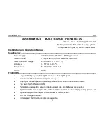
Saswell SAS900MTK-0 Operating Instructions Manual Download Page 11

SAS900MTK-0

A0

10

1.

Move SYSTEM switch to COOL position.

2.

Press ▼ to adjust thermostat setting below room temperature. The blower should come on

immediately, followed by cold air circulation. If the COOL ON display is flashing, the 1st
stage compressor is at off-time cycle protection

3.

Both stages of cooling system will begin to operate when the set point is 3

℉(

2

℃)

below

ambient AUX +2 display will be display. If +2 display is flashing, the second stage will
delay 15 minutes before starting (Note: See Configuration menu item 1)

4.

Press ▲ to adjust temperature setting above room temperature. The cooling system should

stop operating.If all functions operate properly, the thermostat is installed correctly.

REPLACING BATTERIES

If your thermostat was pre-installed, the batteries may be in place. If the battery icon on the
display is flashing, it indicates that the batteries need to be replaced. When the thermostat
is powered only by battery, the battery icon will flash for approximately 2 months before the
batteries are expected to expire.

Important:

Replace the batteries when the low battery message flashes on the display.

This will keep the thermostat operating properly. With two “AAA” batteries installed, your
thermostat will maintain time and continuously display the temperature during a loss of AC
power.

1.

Place the

COOL/OFF/HEAT

switch in the

OFF

position.

2.

Put the

FAN AUTO/ON

switch in the

AUTO

position.

3.

Gently pull the cover straight off the base.

4.

Install two “AAA” alkaline batteries in battery compartment. Be sure to match the po)

Summary of Contents for SAS900MTK-0

Page 1: ...SAS900MTK 0 A0 1 OPERATING INSTRUCTION SAS900MTK 0...

Page 2: ...acy 1 F or 0 5 C Dimensions 5 1 W X 3 7 H X 1 2 D Color White FEATURES Large LCD display with backlight continuous backlight option Simultaneous heat and cool set point storage Display of room tempera...

Page 3: ...g and electrical codes and ordinances Do not short jumper across terminals on the gas valve or at the system control to test installation This will damage the thermostat and void the warranty Do not s...

Page 4: ...eating and cooling system by removing the fuse or switching the appropriate circuit breaker off 3 Remove the cover of the old thermostat This should expose the wires 4 Label the existing wires from th...

Page 5: ...re setting 2 Lowers temperature setting 3 Selects clock set mode Indicates filter time remaining and selects menu items in the configuration menu 4 Fan control switch ON AUTO 5 System control switch C...

Page 6: ...e thermostat activates auxiliary heating 11 Battery Icon If the Battery Icon is flashing batteries need to be replaced 12 Indicates the thermostat is calling for HEAT or COOL 13 Indicates the current...

Page 7: ...y removing the fuse or switching the appropriate circuit breaker to the OFF position before removing the existing thermostat 1 Turn off power to the heating and cooling system by removing the fuse or...

Page 8: ...ching wire terminals See Wiring Diagrams Section 3 Figure 3 CAUTION Be sure exposed portions of wires do not touch other wires 10 Tighten screws on terminal block Gently tug on each wire to be sure of...

Page 9: ...ystem is an electric heat that REQUIRES the thermostat to turn on the fan on a call for heat place do not cut Jumper1 If your system does not require the thermostat to energize the fan on a call for h...

Page 10: ...e blower should stop immediately HEATING SYSTEM 1 Move the SYSTEM switch to the HEAT position If the auxiliary heating system has a standing pilot be sure to light it 2 Press to adjust thermostat sett...

Page 11: ...tat is installed correctly REPLACING BATTERIES If your thermostat was pre installed the batteries may be in place If the battery icon on the display is flashing it indicates that the batteries need to...

Page 12: ...F position then press and hold the and buttons in a same time for 5 seconds to enter the configuration menu The display will show the first item in the configuration menu Press the button to move to t...

Page 13: ...acklight mode 4 FL 00 00 12 Select filter time in months A selection of 00 deactivates the filter feature 5 FC F F or C Select C or F Readout 6 CL 0 4 TO 4 Select temperature calibration point up to 4...

Page 14: ...duce very accurate temperature control and can be set to your personal preference FA cycles the heat pump system at a 0 5 F differential and Aux heating at 2 0 F below first stage on SL cycles the hea...

Page 15: ...g is 00 5 Select F or C readout Changes the display readout to Centigrade or Fahrenheit as required The default setting is F 6 Select temperature recalibration This feature allows you to adjust the di...

Page 16: ...ating the thermostat is in the 1st stage heating or cooling mode MANUAL OPERATION 1 TEMPERATURE OVERRIDE Press the and buttons until the temperature you want is displayed The thermostat will override...

Page 17: ...g Press the button once The display will now show the correct day of the week and the correct time TROUBLESHOOTING If a voltage spike or static discharge blanks out the display or causes erratic therm...

Page 18: ...dition occurs If the heat works intermittently contact the furnace manufacturer or local service person for assistance Diagnostic Set System Switch to Heat and raise the Setpoint above room temperatur...

Page 19: ...of one 1 year from the date of purchase unless specified in writing for a different period Prior to returning this product to us the purchaser shall give us notice in writing stating how this product...

Page 20: ...DAMAGES This warranty gives you specific legal rights and you also have other rights which vary from state to state Some states do not allow the exclusion or limitation of incidental or consequential...

Reviews: