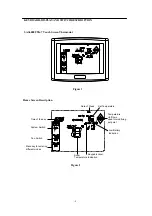
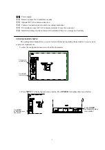
Saswell SAS6000UTK-7 Installation And Operation Instructions Manual Download Page 4


- 4 - 

(14)


Press 

UP

 and 

DOWN

 for setting current time clock or setting time in programming or changing       

selections in configuration menu or setting the time when a temporary hold period will end 

(15)


Emergency

” flashes when system mode is set “

EMER

” 

“ 

Using Schedule

” displays when thermostat is operating under presetting schedule 

“ 

Permanent Hold

” displays when thermostat is in permanent hold setting temperature period 

 Temporary Hold

” displays when thermostat is in temporary hole setting temperature period 

(16)      displays when first stage cooling activate     

displays when both first stage cooling and second stage cooling activate       


(17)   displays when first stage heating activate 

displays when both first stage heating and second heating activate 
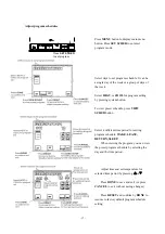
(18)


displays when Auxiliary heating or Emergency heating activate 

(19)


      displays when circulating fan activate 

(20)


TECHNICIAN SET UP: USE UP AND DOWN FOR SURRENT SELECTION AND NEXT 

STEP PREVIOUS STEP KEY TO THE NEXT PREVIOUS STEP

” displays to help technician 

how to operate in configuration mode 

(21)


  Indicate current status of the thermostat 

(22)


  “

Chg Filter

” displays indicate changing filter count back has expired   

(23)


  “

Comp Dly

” displays when compressor delay lock out activate 

(24)


  “

Chg UV

” displays when changing UV duration days has expired 
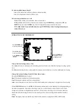
 

INSTALLATION 


1.


Pull the thermostat body off the thermostat base. Forcing or prying on the thermostat will cause 

damage to the unit. 

2.


Place base over hole in wall and mark mounting hole locations on wall using base as a template 

3.


Move base out of the way. Drill mounting holes. If you are using existing mounting holes and the 

holes drilled are too large and do not allow you to tighten base snugly, use plastic screw anchors to 

secure the base.   

4.


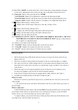
Fasten base snugly to wall using mounting holes shown in Figure 3 and two mounting screws. 

Leveling is for appearance only and will not affect thermostat operation. 

5.


Connect wires to terminal block on base using appropriate wiring schematic (See Figure 5) 

6.


Carefully line the thermostat up with the base and snap into place. 

Battery Location 

Batteries are optional (to provide backup power) if your thermostat was wired to run on AC power 

when installed. 

2 “AA” alkaline batteries are included in the thermostat at the factory with a battery tag to prevent 

power drainage.   

Battery replacement 

Install fresh batteries immediately when the 

Low Batt

 warning begins flashing. The warning flashes 

about 60 days before batteries are depleted. Even if the warning does not appear, you should replace 

batteries once a year, or before leaving home for more than 1 month 

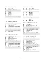
To replace batteries, set system to OFF, remove thermostat from wall and install the batteries in the 

rear along the top of the thermostat. (See figure 4)


Summary of Contents for SAS6000UTK-7

Page 1: ...Auto change over Permanent user setting retention during power loss no batteries are required Optional 7 day programming and non programmable Optional temperature display of Celsius or Fahrenheit sca...

Page 2: ...rmostat Home Screen Description Figure 2 Figure 1 Time of the day System Switch Fan Swtich Menu key for entering different modes Date of Week Set Temperature Room Temperature Temperature Up Down used...

Page 3: ...s CLEAN DISPLAY for entering 30 second count back time for cleaning the display Press PREVIOUS STEP for going back to last configuration menu item 9 Press SET SCHED for setting schedule for each days...

Page 4: ...xpired INSTALLATION 1 Pull the thermostat body off the thermostat base Forcing or prying on the thermostat will cause damage to the unit 2 Place base over hole in wall and mark mounting hole locations...

Page 5: ...y Y Compressor contactor G Fan relay C S1 24VAC common remote sensor 3 4 S2 Remote sensor RC Power 1 RH RH RC joined by jumper W Heat Relay Y Compressor contactor G Fan relay C S1 24VAC common remote...

Page 6: ...ing B Changeover valve energized in cooling G Fan relay C S1 24VAC common remote sensor 3 S2 Remote sensor L Equipment monitor 5 RC Power 1 RH RH RC joined by jumper Y1 Compressor relay 1 E Emergency...

Page 7: ...there is no emergency heat relay CONFIGURATION MENU The configuration menu allows you to set certain thermostat operating characteristics to your system or personal requirements To enter the configur...

Page 8: ...T STEP AUMOdE HA HA HE HA Fossil fuel backup heat HE Electric backup heat NA NA 5 NEXT STEP CHANGE 0 0 1 0 Manual changeover 1 Auto changeover 6 NEXT STEP DbaNd 3 2 3 4 5 6 7 8 9 Auto changeover dead...

Page 9: ...elect second stage cooling rate 18 NEXT STEP FILTER 00 00 12 Select filter replacement run time 19 NEXT STEP UVLAMP UF UO or UF Select UV lamp replacement run time 20 NEXT STEP CLOCK 12 24 12 Selectio...

Page 10: ...ecovery operation The thermostat has an intelligent recovery function that brings your room temperature to the set temperature at exactly the pre set time by turning on the heating earlier Select ON t...

Page 11: ...1 HP2 2H setting in system type option Second stage heating rate Second stage heating will activate Hcycle H2sp below first stage heating 16 Select second stage cooling rate This option apply only to...

Page 12: ...en remote sensor option menu item 20 is set 2 0 No heat pump compressor lockout 15 20 25 30 35 40 heat pump compressor lockout temperature With fossil fuel backup See menu item 3 Auxiliary heat type o...

Page 13: ...onal air cleaning Choose the System Setting Cool Off Heat Emer Auto Press the SYSTEM button to select Heat Thermostat controls only the heating system Cool Thermostat controls only the cooling system...

Page 14: ...am schedule What ever temperature you set will be maintained 24 hours a day until you manually change it or press RUN SCHED to cancel Hold and resume the program schedule Vacation Hold Override This f...

Page 15: ...set to 1 or 2 INFO will display in home screen Press INFO for inquiring outside temperature Thermostat will display outside temperature Inquiry for filter count back time This operation is only avail...

Page 16: ...e configuration menu item 6 Intelligent Recovery operation Compressor protection See configuration menu item 10 Select compressor lockout delay Heat Pump Temperature Lockout See configuration menu ite...

Page 17: ...reset schedule press VIEW SCHED button Select 4 different time period for setting program schedule WAKE LEAVE RETURN SLEEP When viewing the program you can view the preset program schedule by selectin...

Page 18: ...rogram The Heating and Cooling Program schedules below allow you to pencil in your own program times and temperatures Keep the following guidelines in mind when planning your program In Heating lower...

Page 19: ...19 CUSTOMER ASSISTANCE After reading this guide if you have any question about the operation of your thermostat please contact your installer or service provider...

Page 20: ...20...

Reviews: