background image

– 2 –

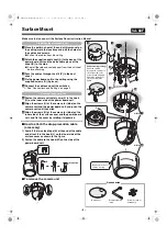
Surface Mount

Make sure to also consult the Surface Cover Instruction Manual.

1

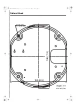
Place the pattern sheet at the end of this manual on 
the ceiling, mark the locations and drill the holes for 
the cables and screws.

Pull out the cables from the ceiling.

2

Attach the supplied dust sheet (A) to the base of the 
power board unit and the detachable piece of the 
sheet (B) to the side.

Peel off the release-coated paper from the dust sheet 
before attaching.

3

Pass the cables through the slit (C) in the dust 
sheet.

4

Fix the power board unit to the ceiling using the 
supplied screws (D) (4 places).

5

Connect the cables and set the switches.

See “Connections and Settings” on page 5.

6

Fasten the camera unit safety wire (F) to the hook 
(G) on the inner side of the power board unit.

7

Align the arrows (H) of the same color (blue) on the 
camera unit and the power board unit, and push the 
camera unit until they click.

8

Align the arrows (H) of the same color (blue) on the 
inner side of the surface cover and the power board 
unit, and fix the cover by rotating it clockwise.

How to attach the drop-prevention cable 
(accessory)

1) Peel off the two-sided tape (K) at the end of the cable 

and attach it to the hook (L) on the inner side of the 
surface cover as shown in the figure.

2) Fasten the cable to the hook (M) on the side of the 

power board unit.

To remove the camera unit

1. Installing the power board unit

2. Mounting the camera unit

M

K

L

Protrusion

2

1

3

6

4

E

A

A

B

B

B

B

D

D

C

G

F

5

A

A

H; Blue 

8

H; Blue 

7

Removed in case of 
surface routing.

Surface routing (ceiling)

Pass the cables 
through the cable hole 
(E) at the side of the 
power board unit, and 
attach the dust sheet 
(A) as shown in the 
figure.

VA-80F

Accessories

Dust sheet

Drop-prevention 
cable

Screw (for power 
board unit)

L5BU2_XE(INSTALLATION).book  2 ページ  2007年8月1日 水曜日 午前11時7分

Summary of Contents for VCC-9500

Page 1: ...eiling Mount Closed Type 3 In ceiling Mount Open Type 4 Connections and Settings 5 Address Settings Table 7 Pattern Sheet inserted at the end of this manual CAUTION For VA 80S Power Borard Unit ALL POLE MAINS SWITCH with a contact separation of at least 3mm in each pole shall be incorporated in the electrical installation of the building Important Be careful when opening holes for installing the u...

Page 2: ...P Attachment VA 80A Outdoor Housing VA 80EX Surface Cover VA 80F Clear Dome Cover VA CM8C Smoked Dome Cover VA CM8S Indoor Type Outdoor Type In ceiling Mount Surface Mount P3 P4 P2 Refer to the instruction manual supplied with each product Refer to the instruction manual supplied with each product Power Board Unit VA 84S for AC24V VA 80S for AC230V Power Board Unit VA 84S for AC24V VA 80S for AC23...

Page 3: ...lue on the camera unit and the power board unit and push the camera unit until they click 8Align the arrows H of the same color blue on the inner side of the surface cover and the power board unit and fix the cover by rotating it clockwise How to attach the drop prevention cable accessory 1 Peel off the two sided tape K at the end of the cable and attach it to the hook L on the inner side of the s...

Page 4: ... bracket top hook F 5Connect the video cable and pass the connection cables through the bracket 6Insert the bracket into the ceiling hole and fix it using screws G 2 places 7Connect the cables and set the switches See Connections and Settings on page 5 8Align the arrows C of the same color blue on the camera unit and the inner side of the bracket and push the camera unit until they click 9Align th...

Page 5: ...he connection cables through the slit in the dust sheet E and connect the video cable 7Insert the bracket into the ceiling hole and fix it using screws F 2 places 8Connect the cables and set the switches See Connections and Settings on page 5 9Align the blue sticker B on the bracket and the arrow B of the same color on the camera unit and then push the camera unit until they click ÀAlign the SANYO...

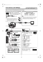
Page 6: ...fter connection always install the supplied power terminal cover A for safety reasons Ground Neutral Live Monitor Connection Supported coaxial cables Using different cables from those specified here may attenuate the video and or sync signals and interfere with correct transmission RG 59U coaxial cables can be used when distance between devices is short but not in duct or aerial routing Cable type...

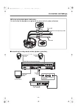
Page 7: ...m input output cables Video cable A RS 485 B DO NOT CONNECT TO PHONE LINE 1 IN OUT MONITOR OUT MON2 2 3 4 5 6 7 8 9 10 11 12 13 14 15 16 MAIN VIDEO A B TELEMETRY 1 16 Video input terminal Camera Camera Video input terminal Monitor sold separately Video input terminal Terminator switch Communication conversion connectors System controller sold separately Digital video recorder sold separately L5BU2...

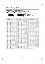
Page 8: ...88 m m m m 61 189 m m m m m 62 190 m m m m m 63 191 m m m m m m 64 192 m 65 193 m m 66 194 m m 67 195 m m m 68 196 m m 69 197 m m m 70 198 m m m 71 199 m m m m 72 200 m m 73 201 m m m 74 202 m m m 75 203 m m m m 76 204 m m m 77 205 m m m m 78 206 m m m m 79 207 m m m m m 80 208 m m 81 209 m m m 82 210 m m m 83 211 m m m m 84 212 m m m 85 213 m m m m Address Camera No Switch No Protocol SANYO PELCO...

Page 9: ...Pattern Sheet 186 7 3 166 6 5 4 φ4 5 0 2 P D φ168 6 6 Scale 1 1 Unit mm inch L5BU2_XE INSTALLATION book 0 ページ 2007年8月1日 水曜日 午前11時7分 ...

Page 10: ...L5BU2_XE INSTALLATION book 1 ページ 2007年8月1日 水曜日 午前11時7分 ...

Page 11: ...MEMO L5BU2_XE INSTALLATION book 2 ページ 2007年8月1日 水曜日 午前11時7分 ...
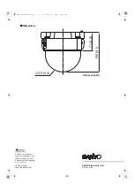
Page 12: ... recyclé Impreso en papel reciclado Gedruckt auf Recyclingpapier 使用再生纸印刷 1AC6P1P3149 A L5BU2 XE 0807KP HS SANYO Electric Co Ltd Printed in China b Dimensions 156 6 1 71 2 8 φ136 5 4 Unit mm inch L5BU2_XE INSTALLATION book 1 ページ 2007年8月1日 水曜日 午前11時7分 ...

Reviews: