


– 6 –
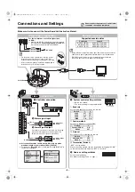
Connections and Settings
■
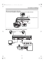
Connections for using coaxial control (System connection)
■
To prevent electromagnetic interference
Be sure to attach the clamping cores supplied with the camera unit to the cables as illustrated.
Power cable
Control and alarm input/output cables
Video cable
A RS-485 B
DO NOT CONNECT TO PHONE LINE
1
IN
OUT
MONITOR OUT
MON2
2
3
4
5
6
7
8
9
10
11
12
13
14
15
16
MAIN
VIDEO
A
B
TELEMETRY
(1 - 16)
Video input
terminal
Camera
Camera
Video input
terminal
Monitor
(sold separately)
Video input
terminal
Terminator
switch
Communication conversion
connectors
System controller
(sold separately)
Digital video recorder (sold separately)
L5BU2_XE(INSTALLATION).book 6 ページ 2007年8月1日 水曜日 午前11時7分


