background image

2

English

IMPORTANT! 

Please Read Before Starting

This air conditioning system meets strict safety and oper-
ating standards. As the installer or service person, it is an
important part of your job to install or service the system
so it operates safely and efficiently.

For safe installation and trouble-free operation, you
must:

!

Carefully read this instruction booklet before beginning.

!

Follow each installation or repair step exactly as
shown.

!

Observe all local, state, and national electrical codes.

!

Pay close attention to all warning and caution notices
given in this manual.

This symbol refers to a haz-
ard or unsafe practice which
can result in severe personal
injury or death.

This symbol refers to a haz-
ard or unsafe practice which
can result in personal injury
or product or property dam-
age.

If Necessary, Get Help

These instructions are all you need for most installation
sites and maintenance conditions. If you require help for
a special problem, contact our sales/service outlet or
your certified dealer for additional instructions.

In Case of Improper Installation

The manufacturer shall in no way be responsible for
improper installation or maintenance service, including
failure to follow the instructions in this document.

SPECIAL PRECAUTIONS

When Wiring

ELECTRICAL SHOCK CAN CAUSE
SEVERE PERSONAL INJURY OR DEATH.
ONLY A QUALIFIED, EXPERIENCED ELEC-
TRICIAN SHOULD ATTEMPT TO WIRE
THIS SYSTEM.

• Do not supply power to the unit until all wiring and tub-

ing are completed or reconnected and checked.

• Highly dangerous electrical voltages are used in this

system. Carefully refer to the wiring diagram and these
instructions when wiring. Improper connections and
inadequate grounding can cause 

accidental injury or

death.

• Ground the unit

following local electrical codes.

• Connect all wiring tightly. Loose wiring may cause over-

heating at connection points and a possible fire hazard.

• Install a protective 

leakage breaker

depending on the

installation location (especially a damp or humid loca-
tion). If a 

leakage breaker

is not installed, electric

shock can occur.

When Transporting

Be careful when picking up and moving the indoor and
outdoor units. Get a partner to help, and bend your knees

when lifting to reduce strain on your back. Sharp edges or
thin aluminum fins on the air conditioner can cut your fin-
gers.

When Installing…

…In a Ceiling or Wall

Make sure the ceiling/wall is strong enough to hold the
unit’s weight. It may be necessary to construct a strong
wood or metal frame to provide added support.

…In a Room

Properly insulate any tubing run inside a room to prevent
“sweating” that can cause dripping and water damage to
walls and floors.

…In Moist or Uneven Locations

Use a raised concrete pad or concrete blocks to provide
a solid, level foundation for the outdoor unit. This pre-
vents water damage and abnormal vibration.

…In an Area with High Winds

Securely anchor the outdoor unit down with bolts and a
metal frame. Provide a suitable air baffle.

…In a Snowy Area (for Heat Pump-type Systems)

Position the outdoor unit in a protected location

where snow will not blow into it.

Install the outdoor unit on a raised platform that is

higher than drifting snow. Provide snow vents.

When Connecting Refrigerant Tubing

• Use the flare method for connecting tubing.
• Apply refrigerant lubricant to the matching surfaces of

the flare and union tubes before connecting them, then
tighten the nut with a torque wrench for a leak-free con-
nection.

• Check carefully for leaks before starting the test run.

When Servicing

• Turn the power OFF at the main power box (mains)

before opening the unit to check or repair electrical
parts and wiring.

• Keep your fingers and clothing away from any moving

parts.

• Clean up the site after you finish, remembering to

check that no metal scraps or bits of wiring have been
left inside the unit being serviced.

Others

• Ventilate any enclosed areas when installing or testing

the refrigeration system. Escaped refrigerant gas, on
contact with fire or heat, can produce dangerously toxic
gas.

• Confirm upon completing installation that no refrigerant

gas is leaking. If escaped gas comes in contact with a
stove, gas water heater, electric room heater or other
heat source, it can produce dangerously toxic gas.

• Do not install only a single indoor unit.

WARNING

WARNING

CAUTION

CAUTION

08-253 CMRV3146EH_OU EN  10/14/08  2:39 PM  Page 2

Summary of Contents for SAP-CMRV1926EH

Page 1: ...ING A HOME AUTOMATION DEVICE 24 8 INSTALLATION CHECK SHEET 24 9 ELECTRIC WIRING DIAGRAM 24 INSTALLATION INSTRUCTIONS Model Combinations Combine indoor and outdoor units only as listed below Indoor Unit Outdoor Unit Combine indoor and outdoor units only as listed in the combination tables for 2 room 3 room or 4 room outdoor unit as shown in its respective manual Power Source 50 Hz single phase 220 ...

Page 2: ...shock can occur When Transporting Be careful when picking up and moving the indoor and outdoor units Get a partner to help and bend your knees when lifting to reduce strain on your back Sharp edges or thin aluminum fins on the air conditioner can cut your fin gers When Installing In a Ceiling or Wall Make sure the ceiling wall is strong enough to hold the unit s weight It may be necessary to const...

Page 3: ...erial If you wish to purchase these materials separately from a local source you will need 1 Deoxidized annealed copper tube for refrigerant tubing as detailed in Table 2 Cut each tube to the appropriate lengths 30 cm to 40 cm to dampen vibration between units Table 2 2 Foamed polyethylene insulation for the specified copper tubes as required to precise length of tub ing Wall thickness of the insu...

Page 4: ...elect a location that will hold the weight of the unit select a location where tubing and drain hose have the shortest run to the outside Fig 1 allow room for operation and maintenance as well as unrestricted air flow around the unit Fig 2 install the unit within the maximum elevation difference H1 H2 H3 H4 above or below the outdoor unit and within a total tubing length L1 L2 L1 L2 L3 L1 L2 L3 L4...

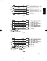
Page 5: ... ø12 70 ø6 35 ø9 52 B ø9 52 A Outdoor unit Indoor unit SAP KMRV74EH KMRV94EH KMRV124EH SAP KMRV76EH KMRV96EH KMRV126EH SAP KRV96EHDS KRV126EHDS SAP KRV184EH SAP KRV186EH ø9 52 ø6 35 ø9 52 ø6 35 ø9 52 B ø9 52 A Outdoor unit Indoor unit SAP KMRV74EH KMRV94EH KMRV124EH SAP KMRV76EH KMRV96EH KMRV126EH SAP KRV96EHDS KRV126EHDS SAP KMRV74EH KMRV94EH KMRV124EH SAP KMRV76EH KMRV96EH KMRV126EH SAP KRV96EHD...

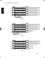
Page 6: ...ø9 52 ø6 35 ø9 52 ø6 35 ø9 52 ø6 35 C ø9 52 B ø9 52 A Outdoor unit Indoor unit SAP KMRV74EH KMRV94EH KMRV124EH SAP KMRV76EH KMRV96EH KMRV126EH SAP KRV96EHDS KRV126EHDS SAP KMRV74EH KMRV94EH KMRV124EH SAP KMRV76EH KMRV96EH KMRV126EH SAP KRV96EHDS KRV126EHDS SAP KMRV74EH KMRV94EH KMRV124EH SAP KMRV76EH KMRV96EH KMRV126EH SAP KRV96EHDS KRV126EHDS B Fig 4c ø12 70 Union ø9 52 Flare A joint for connecti...

Page 7: ...AP KMRV74EH KMRV94EH KMRV124EH SAP KMRV76EH KMRV96EH KMRV126EH SAP KRV96EHDS KRV126EHDS ø9 52 ø9 52 ø6 35 D Outdoor unit Indoor unit SAP KMRV74EH KMRV94EH KMRV124EH SAP KMRV76EH KMRV96EH KMRV126EH SAP KRV96EHDS KRV126EHDS SAP KRV244EH SAP KRV246EH ø12 70 Union ø9 52 Flare ø9 52 ø12 70 Locally purchased C Fig 4f ø15 88 Union ø12 70 Flare ø12 70 ø15 88 Locally purchased ø9 52 ø9 52 ø6 35 ø9 52 ø6 35...

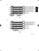
Page 8: ... ø12 70 Flare ø12 70 ø9 52 Supplied Reducer ø9 52 ø9 52 ø6 35 ø9 52 ø6 35 ø12 70 ø6 35 C ø12 70 B ø12 70 A SAP KMRV74EH KMRV94EH KMRV124EH SAP KMRV76EH KMRV96EH KMRV126EH SAP KRV96EHDS KRV126EHDS SAP KMRV74EH KMRV94EH KMRV124EH SAP KMRV76EH KMRV96EH KMRV126EH SAP KRV96EHDS KRV126EHDS ø9 52 ø9 52 ø6 35 D Outdoor unit Indoor unit SAP KMRV74EH KMRV94EH KMRV124EH SAP KMRV76EH KMRV96EH KMRV126EH SAP KR...

Page 9: ...4EH KMRV94EH KMRV124EH SAP KMRV76EH KMRV96EH KMRV126EH SAP KRV96EHDS KRV126EHDS SAP KRV244EH SAP KRV246EH ø9 52 Union ø12 70 Flare ø12 70 ø9 52 Supplied Reducer E Fig 4l ø15 88 Union ø12 70 Flare ø12 70 ø15 88 Locally purchased ø9 52 ø9 52 ø6 35 ø12 70 ø6 35 ø15 88 ø6 35 C ø12 70 B ø12 70 A SAP KRV184EH SAP KRV186EH SAP KMRV74EH KMRV94EH KMRV124EH SAP KMRV76EH KMRV96EH KMRV126EH SAP KRV96EHDS KRV1...

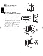
Page 10: ...level concrete pad concrete block 15 40 cm beams or equal a minimum of 15 cm above ground level to reduce humidity and protect the unit against possible water damage and decreased service life Fig 5c install cushion rubber under unit s feet to reduce vibration and noise Fig 5d use lug bolts or equal to bolt down unit reducing vibration and noise install in a location where no antenna of a televisi...

Page 11: ... 75 73 70 70 70 70 A Service valve on narrow tube side Outer diameter ø6 35 Service valve on wide tube side Outer diameter ø12 70 Service valve on wide tube side Outer diameter ø9 52 A 608 136 12 900 345 320 369 85 740 18 150 72 70 51 113 75 70 114 A Service valve on narrow tube side Outer diameter ø6 35 Service valve on wide tube side Outer diameter ø9 52 A Fig 6d unit mm Fig 6c Fig 6b 1 SAP CMRV...

Page 12: ...e below are spaces that are required in order to maintain performance Install in a location where the dimensions indicated by are ensured and where 2 or more faces of the unit are unobstructed In principle the top direction should be unobstructed Indoor unit C Indoor unit B Indoor unit A Indoor unit D Service space Power breaker Ground wire not provided Ensure 15cm of space if a drain hose is to b...

Page 13: ... outdoor units In this method the copper tubes are flared at each end and connected with flare nuts 3 4 Flaring Procedure with a Flare Tool 1 Cut the copper tube to the required length with a tube cutter It is recommended to cut approx 30 50 cm longer than the tubing length you estimate 2 Remove burrs at the end of the copper tube with a tube reamer or file This process is important and should be ...

Page 14: ...oper connection align the union tube and flare tube straight with each other then screw in the flare nut lightly at first to obtain a smooth match Fig 13 3 6 Tubing Connections a Temporary connection Screw in 3 5 rotations by hand Fig 14 b To fasten the flare nuts apply specified torque as Table 4 NOTE NOTE Reamer Copper tubing Fig 9 Flare tool Flare nut Copper tubing Fig 11 Apply refrigerant lubr...

Page 15: ...p the tubing bundle to wall using 1 clamp approx every 120 cm Do not wind the armoring tape too tightly since this will decrease the heat insulation effect Also be sure the con densation drain hose splits away from the bundle and drips clear of the unit and the tubing 3 9 Finishing the Installation After finishing insulating and taping over the tubing use sealing putty to seal off the hole in the ...

Page 16: ...service valve Fig 20 Fig 20 Fig 21 CAUTION Be sure to use a manifold valve for air purging If it is not available use a stop valve for this purpose The Hi knob of the manifold valve must always be kept closed CAUTION CAUTION Before using the vacuum pump adapter read the vacuum pump adapter manual and use the adapter correctly In order to prevent charging errors with the air conditioner that uses R...

Page 17: ...k then apply the vacuum again 6 With a hex wrench turn the valve stem on the nar row tube service valve counter clockwise by 90 degrees 1 4 turn for 10 seconds and then turn the stem clockwise to close it again 7 With a standard screwdriver turn the wide tube service valve stem counterclockwise to fully open the valve 8 Turn the narrow tube service valve stem counter clockwise to fully open the va...

Page 18: ...blem 4 Disconnect the manifold gauge and the inter unit tubes and attach the caps and flare nuts At this point pump down is completed If the caps and flare nuts are not reattached there is the danger of gas leakage Refer to Fig 24 If pump down is not possible If the Air Conditioner cannot be operated because of a malfunction or other cause use a refrigerant recovery device to recover the refrigera...

Page 19: ... moving parts of the fan 6 Unauthorized changes in the internal wiring can be very dangerous The manufacturer will accept no responsibility for any damage or misoperation that occurs as a result of such unauthorized changes 5 2 Recommended Wire Length and Diameter Regulations on wiring diameter differ from locality to locality For field wiring requirements please refer to your local elec trical co...

Page 20: ...rical noise caused by high tension Otherwise electrical shock may occur Place a dedicated ground more than 2 meters away from other grounds and do not have it shared with other electric appliances WARNING Fig 25b 4 indoor units with SAP CMRV2446 CMRV3146 INDOOR UNIT 4 3 2 1 3 2 1 2 1 UNIT A Terminal L N A B C Terminal 9P Terminal 2P OUTDOOR UNIT Grounding line INDOOR UNIT 4 3 2 1 6 5 4 UNIT B Term...

Page 21: ...minal screw 4 Shape the loop wire properly place it on the termi nal plate and fix it securely with the removed termi nal screw using a screwdriver For stranded wiring 1 Cut the wire end with a cutting pliers then strip the insulation to expose the stranded wiring about 10 mm and tightly twist the wire ends Figs 28 and 29 2 Using a screwdriver remove the terminal screw s on the terminal plate 3 Us...

Page 22: ...t tubing that is connected to service valve A bottom of the outdoor unit B is the indoor unit with refrigerant tubing that is connected to service valve B second from the bottom of the outdoor unit C is the indoor unit with refrigerant tubing that is connected to service valve C third from the bottom of the outdoor unit refrigerant tubing that is connected to service valve D top of the outdoor uni...

Page 23: ... indoor unit If 2 units are operated simultaneously it is not possible to correctly check for errors in tubing and wiring If the room temperature is 15 C or below it may not be possible to check for tubing errors with cooling operation If this occurs perform heating operation for each unit individually and check that warm air is dis charged from each unit If there is cold air mixed in with the war...

Page 24: ...lose the hole in the wall All service valves are fully open Remote controller signals are being positively received 9 Electric Wiring Diagram Diagrama de cableado eléctrico Diagramme de câblage électrique Elektrisches Schaltbild Diagramma dei circuiti elettrici Diagrama da fiação elétrica È È Á ÁÚ Ú Ì ÌÌ Ì Ë ËÏ Ï ÂÎ ÎÙ ÙÚ ÚÈ ÈÎ Î Î Î Ï Ïˆ ˆ ˆ ˆÛ ÛË Ë Indoor Unit Unidad interior Appareil intérieur...

Page 25: ...5 1 1 2 2 3 3 4 4 5 5 WHT BLU BLU BLU BLU SW ASSY WHT FLAP3 PANEL MOTOR 1 1 2 2 3 3 4 4 5 5 1 2 3 4 1 1 2 2 3 3 4 4 5 5 PANEL WHT WHT WHT GRY GRY GRY GRY FLAP1 FLAP MOTOR UPPER FLAP MOTOR LOWER 1 1 2 2 3 3 4 4 5 5 6 6 7 7 8 8 9 9 10 10 1 1 2 2 3 3 4 4 5 5 FLAP1 WHT WHT WHT RED WHT FLAP2 WHT GRY GRY GRY GRY FM DC FAN MOTOR DCM BLU BLU RED BLK YEL BLU WHT WHT 1 1 2 2 3 3 4 4 5 5 6 6 WHT RED BLK YEL ...

Page 26: ...10 2 1 3 4 W W SICOM2 SICOM2 SI C W BLK GRY RED ORG YEL 1 2 3 4 1 2 3 4 5 5 MV2 MAGNETIC COIL 1 2 3 4 1 2 3 4 5 5 MV2 1 2 3 4 1 2 3 4 C TH YEL YEL YEL YEL CW THERMISTOR CN THERMISTOR W W W W W 1 2 3 E 1 RED PNK 8FA 2 5257 57000 0 Fig 34b WHT WHT L2 L1 WHT WHT WHT 2P CONNECTOR 2 1 2 1 REACTANCE COIL THERMISTOR COMP COIL OUTDOOR A TH B TH COMPRESSOR THERMISTOR OUTDOOR THERMISTOR AW THERMISTOR W W DE...

Page 27: ...LK YEL GRY BLK YEL GRY BLK YEL GRY BLK YEL GRY 8FA 2 5257 57100 0 Fig 34c WHT WHT L2 L1 WHT WHT WHT 2P CONNECTOR 2 1 2 1 REACTANCE W W HEATER1 HEATER0 CRANKCASE HEATER COIL THERMISTOR COMP COIL OUTDOOR A TH B TH COMPRESSOR THERMISTOR OUTDOOR THERMISTOR AW THERMISTOR W W DEF1 DEF0 W W RV1 RV0 DEF COIL DEFROST VALVE 2 1 2 1 RV COIL 4WAY VALVE AN THERMISTOR BN THERMISTOR BW THERMISTOR BLK 2P CONNECTO...

Page 28: ...des abréviations Italiano Português EÏÏËÓÈÎ EÏÏËÓÈÎ 1 2 3 4 5 6 7 8 9 10 11 BLK BLU BRN GRN YEL GRY ORG PNK RED VLT WHT YEL BEDEUTUNG SCHWARZ BLAU BRAUN GRAU ORANGE ROSA ROT VIOLETT WEISS GELB Bedeutung der Abkürzungen ABKÜRZUNG GRÜN GELB 1 2 3 4 5 6 7 8 9 10 11 BLK BLU BRN GRN YEL GRY ORG PNK RED VLT WHT YEL Significato delle abbreviazioni ABBREV SIGNIFICATO NERO BLU MARRONE VERDE GIALLO GRIGIO A...

Reviews: