background image

4

English

1-5.  Additional Materials Required for Installation

1.

Refrigeration (armored) tape

2.

Insulated staples or clamps for connecting wire

(See local codes)

3.

Putty

4.

Refrigeration lubricant

5.

Clamps or saddles to secure refrigerant tubing

2.  Installation Site Selection

2-1.  Indoor Unit

AVOID:

G

direct sunlight.

G

nearby heat sources that may affect performance of the

unit.

G

areas where leakage of flammable gas may be expected.

G

placing or allowing any obstructions near the Air 

Conditioner inlet or outlet.

G

installing in rooms that contain instant-on (rapid-start) 

fluorescent lamps. (These may prevent the Air Conditioner

from receiving signals.)

G

places where large amounts of oil mist exist.

G

installing in locations where there are devices that 

generate high-frequency emissions.

DO:

G

select an appropriate position from which every corner of

the room can be uniformly cooled. (High on a wall is best.)

G

select a location that will hold the weight of the unit.

G

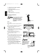
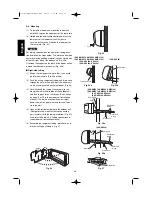
select a location where tubing and drain hose have the

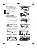
shortest run to the outside. (Fig. 1)

G

allow room for operation and maintenance as well as 

unrestricted air flow around the unit. (Fig. 2)

G

install the unit within the maximum elevation difference 

(H1, H2, H3, H4) above or below the outdoor unit and 

within a total tubing length (L1+L2, L1+L2+L3,

L1+L2+L3+L4) from the outdoor unit as detailed in Table 3

and Fig. 3a.

Drain hose

Indoor unit

Outside drainage

Fig. 1

5 cm

min.

5 cm
min.

15 cm min.

Front View

Fig. 2

INDOOR
UNIT (1)

INDOOR
UNIT (4)

INDOOR
UNIT (3)

INDOOR
UNIT (2)

Tubing length (L1)

L2

L3

L4

H2

H3

H4

OUTDOOR
UNIT

Elevation
difference (H1)

Fig. 3a

WARNING

To prevent abnormal heat generation

and the possibility of fire, do not

place obstacles, enclosures and

grilles in front of or surrounding the

air conditioner in a way that may

block air flow.

Indoor unit

Floor level

Wall

Minimum height 
from floor level

1.5 m

Fig. 3b

For stable operation of the air

conditioner, do not install

wall-mounted type indoor

units less than 1.5 m from

floor level.

CAUTION

07-370 CMRV3146EH_IU ENG  2/6/08  1:31 PM  Page 4

Summary of Contents for SAP-CMRV1426EH

Page 1: ...pe the Indoor Side Tubing 3 6 Wiring Instructions 3 7 Wiring Instructions for Inter unit Connections 3 8 Mounting 3 9 Drain Hose 4 MULTIPLE SWITCH ON THE REMOTE CONTROL UNIT INDOOR UNIT TYPES SAP KRV184EH KRV244EH SAP KRV186EH KRV246EH SAP KRV96EHDS 19 5 HOW TO TEST RUN THE AIR CONDITIONER 20 6 REMOTE CONTROL UNIT INSTALLATION POSITION 22 6 1 Mounting on a Wall 7 ADDRESS SWITCH 23 7 1 Address Sett...

Page 2: ...ng the indoor and outdoor units Get a partner to help and bend your knees when lifting to reduce strain on your back Sharp edges or thin aluminum fins on the air conditioner can cut your fin gers When Installing In a Ceiling or Wall Make sure the ceiling wall is strong enough to hold the unit s weight It may be necessary to construct a strong wood or metal frame to provide added support In a Room ...

Page 3: ...led copper tube for refrigerant tubing as detailed in Table 2 Cut each tube to the appropriate lengths 30 cm to 40 cm to dampen vibration between units Table 2 2 Foamed polyethylene insulation for the specified copper tubes as required to precise length of tub ing Wall thickness of the insulation should be not less than 8 mm 3 Use insulated copper wire for field wiring Wire size varies with the to...

Page 4: ...hat will hold the weight of the unit G select a location where tubing and drain hose have the shortest run to the outside Fig 1 G allow room for operation and maintenance as well as unrestricted air flow around the unit Fig 2 G install the unit within the maximum elevation difference H1 H2 H3 H4 above or below the outdoor unit and within a total tubing length L1 L2 L1 L2 L3 L1 L2 L3 L4 from the ou...

Page 5: ...isture in the air inside the tubing may condense into water droplets and lead to water contamination of the refrigerant circuit G In order to prevent insulation breakdown and ground faults do not allow wiring ends to come in contact with rainwater or be subjected to condensation or dew G Apply sufficient thermal insulation to the refrigerant tubing and drain pipes If total tubing length becomes 45...

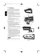
Page 6: ...measure down from the ceiling Wait until after cutting the hole before attaching the rear panel to the wall 2 Determine which side of the unit you should make the hole for tubing and wiring Fig 9a 9b or 9c In the case of left rear tubing use the measurement points from the edge of the rear panel for precise placement of the hose outlet Fig 9a 9b or 9c 3 Before making the hole check carefully that ...

Page 7: ...screws provided Fig 13a 13b or 13c If you are not able to line up the holes in the rear panel with the beam locations marked on the wall use rawl plugs or toggle bolts to go through the holes on the panel or drill 5 mm dia holes in the panel over the stud locations and then mount the rear panel 2 Double check with a carpenter s level or tape mea sure that the panel is level This is important to in...

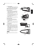
Page 8: ...er part of the grille back into position 2 Make sure that the grille and frame are firmly fitted together by engaging the tabs 3 Attach the thermistor on the grille Fig 17a 4 Close the cover and replace the screw Fig 17a 5 Affix the grille with the 2 previously removed screws Fig 16b 6 Install the air intake grille a Allow the edge of the air intake grille to slide into the top of the indoor unit ...

Page 9: ...g 18b 1 Then insert the tabs on the top of the grille and on the front face into the frame 2 Make sure that the grille and frame are firmly fitted together by engaging the tabs 3 Attach the thermistor on the grille Fig 17a 1 4 Close the cover and replace the screw Fig 17a 1 5 Affix the grille with the 3 previously removed screws Fig 16b 1 6 Install the air intake grille a Allow the edge of the air...

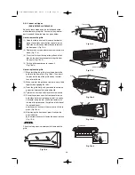
Page 10: ...g both edges of the grille with the frame move the panel horizontally and insert the top and bottom into the frame 3 Press the air discharge outlet firmly with your hand to ensure no gap exists between the main unit and grille 4 Tighten the 2 screws and close the screw covers Also tighten the 3 screws of the frame 5 Grasp the sections near the front panel arms on both sides hold the front panel so...

Page 11: ... of the grille into the frame 2 While aligning both edges of the grille with the frame move the grille horizontally and insert the top and bottom into the frame 3 Press the grille firmly with your hand to ensure no gap exists between the frame and grille 4 Tighten the 2 screws and close the screw covers 5 Grasp the sections near the front panel arms on both sides hold the front panel so that it is...

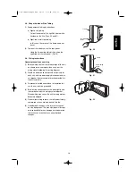
Page 12: ... the tabs on the top of the grille and on the front face into the frame 2 Make sure that the grille and frame are firmly fitted together by engaging the tabs 3 Press the grille firmly with your hand to ensure no gap exists between the frame and grille 4 Tighten the 3 screws and close the screw covers 5 Grasp the sections near the front panel arms on both sides hold the front panel so that it is ne...

Page 13: ...ower outlet to be used exclusively for each unit with a power supply disconnect and cir cuit breaker for overcurrent protection provided in the exclusive line 3 To prevent possible hazard due to insulation fail ure the unit must be grounded 4 Each wiring connection must be done tightly and in accordance with the wiring system diagram Wrong wiring may cause the unit to misoperate or become damaged ...

Page 14: ... 25 4 Route the inter unit wiring from the back of the indoor unit and pull it towards the front for connection Fig 26a 26b 26c or 26d 5 Connect the inter unit wiring to the corre sponding terminals on the terminal plate Fig 26a 26b 26c or 26d while referring to the wiring diagram 6 Be sure to secure the wiring with the pro vided clamp When closing the air intake grille press the bot tom right and...

Page 15: ...ew 4 Shape the loop wire properly place it on the ter minal plate and fix it securely with the removed terminal screw using a screwdriver I For stranded wiring 1 Cut the wire end with a cutting pliers then strip the insulation to expose the stranded wiring about 10 mm and tightly twist the wire ends Figs 30 and 31 2 Using a screwdriver remove the terminal screw s on the terminal plate 3 Using a ri...

Page 16: ...he tubing if necessary to run along the wall in the direction of the outdoor unit and then tape as far as the fittings See Caution on page 10 or 15 in the outdoor unit installation manual The drain hose should come straight down the wall to a point where water runoff won t stain the wall 4 Connect the refrigerant tubing to the outdoor unit After performing a leak test on the connecting part insula...

Page 17: ...ht side Fig 40a Drain hose Slide the drain hose fully onto the drain pan outlet until the drain hose edge is pushed into the insu lation Check that the screw holes in the drain bracket and the drain pan outlet are aligned and securely in contact then fasten them with the screw After attaching the drain hose check that it is attached securely Fig 40c Drain cap Use a Phillips screwdriver to push the...

Page 18: ...ain fitting comes below the stopper as shown in the figure It will be easy to insert when water is added Fig 39d e Align the tabs of the removed cover with the grille tabs and then lower the cover to install it Drain cap Use a Phillips screwdriver to push the drain cap in firmly If it is difficult to push in wet the cap with water first 3 Install the indoor unit on the rear panel 4 Connect the tub...

Page 19: ... unit or operate it until all tubing and wiring to the outside unit are completed Condensation Insulation material Locally purchased must be used Fig 44 Push Fig 42 Slant Drain hose Indoor unit Fig 43 4 Multiple Switch on the Remote Control Unit Indoor Unit Types SAP KRV184EH KRV244EH SAP KRV186EH KRV246EH SAP KRV96EHDS S M Single Multiple switch G Initially the S M switch is set to S Single G Set...

Page 20: ... forced air with the 4 indicator lamps OPERATION lamp TIMER lamp QUIET lamp and ION lamp on the main unit blinking Fig 60 After 3 minutes the system shifts into cooling operation and cool air will start to be felt Cool ing mode test run is unaffected by the room tem perature 3 Press the ON OFF operation button of the remote controller again to stop the test run Fig 59a 4 Finally press the ACL Rese...

Page 21: ...ng in the remote controller clock display area Fig 59b 1 2 Start Cooling mode test run by pressing the ON OFF operation button of the remote controller Fig 59a 1 This starts the fan producing uncooled forced air with the 3 indi cator lamps OPERATION lamp TIMER lamp and LED CLEAN lamp on the main unit blinking Fig 59c 1 or 59c 2 After 3 minutes the system shifts into cooling operation and cool air ...

Page 22: ...tacle between the remote control unit and the air conditioner since a check signal is sent from the remote control unit every 5 minutes 6 1 Mounting on a Wall Before mounting the remote control unit press the ON OFF operation button at the mounting location to make sure that the air conditioner operates from that location The indoor unit should make a beeping sound to indicate that it has received...

Page 23: ...address on the second remote controller Once changed you cannot restore the original address setting of the air con ditioner 1 Switch on the power source 2 Break the address setting tab marked A on the second remote controller to change the address Fig 62 When the tab is removed the address is automatically set to B Fig 63 3 SAP KMRV74EH KMRV94EH KMRV124EH KRV184EH KRV244EH Press and hold the remo...

Page 24: ...r units are installed level and vertically The power and voltage are as specified Inter unit cables are securely inserted into the terminal block Inter unit cables are securely fixed The power cord and inter unit cables are not connected anywhere along their paths The ground wire is securely connected Thermal insulation has been applied to the tubing connections Drain connections are secure and wa...

Reviews: