


-2-
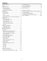
Contents
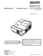
SERVICE MANUAL ....................................................... 1
Contents ........................................................................ 2
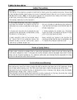
Safety Instructions ......................................................... 3
Specifications ................................................................ 4
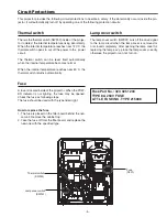
Circuit Protections ......................................................... 5
Thermal switch ........................................................... 5
Fuse ............................................................................ 5
Lamp cover switch ...................................................... 5
Warning temperature and power failure protection .... 6
Maintenance .................................................................. 7
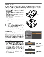
Replacing the filter ...................................................... 7
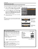
Resetting the filter counter ........................................ 7
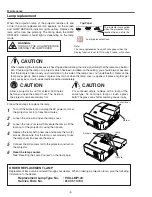
Lamp replacement ...................................................... 8
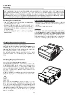
Cleaning ................................................................... 10
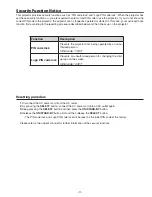
Security Function Notice .............................................. 11
Resetting procedure ................................................ 11
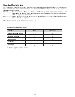
Standby Mode Notice .................................................. 12
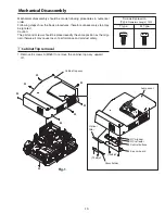
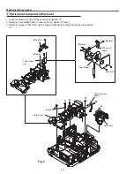
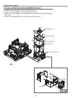
Mechanical Disassembly ............................................. 13
Adjustments ................................................................. 22
Adjustments after parts replacement ........................ 22
Note on main board replacement ............................. 22
Service adjustment menu operation ......................... 22
Circuit adjustments ................................................... 23
Service adjustment data table .................................. 26
Chassis Block Diagrams .............................................. 34
Chassis over view ..................................................... 34
System control .......................................................... 35
Power supply & protection circuit ............................. 36
Fan control circuit ..................................................... 37
Troubleshooting ........................................................... 38
Indicators and projector condition ............................. 38
No power .................................................................. 39
No picture ................................................................. 40
No sound .................................................................. 41
Error log .................................................................... 42
Control Port Functions ................................................. 43
System control (DDP, IC401) ................................... 43
IIC bus D/A converter (Fan control, IC7881) ............ 44
IC Block Diagrams ....................................................... 45
Parts Location Diagrams ............................................. 50
Mechanical Parts List .................................................. 54
Electrical Parts List ...................................................... 55
Diagrams & Drawings ..................................................A1
Parts description and reading in schematic diagram ...A2
Schematic Diagrams ...................................................A3
Printed Wiring Board Diagrams ...................................A9
Pin description of diode, transistor and IC .................A13
Note on Soldering ......................................................A14
Summary of Contents for PDG-DXL2000E
Page 47: ... 47 IC Block Diagrams LV49152V Audio output IC001 LC87F2G08A Sub micom IC4501 ...
Page 48: ... 48 IC Block Diagrams M62393 DAC IC7881 MR4010 Power switching IC631 ...
Page 49: ... 49 IC Block Diagrams PIC18F67J60 Network IC8301 NJW1156 Audio selector IC5101 ...
Page 82: ...Key No Part No Description Key No Part No Description Electrical Parts List 82 KV2 DXL2000E00 ...
Page 83: ...Key No Part No Description Key No Part No Description 83 Electrical Parts List KV2 DXL2000E00 ...
Page 84: ... KV2AC Apr 2011 DC 50 Printed in Japan SANYO Electric Co Ltd ...