


-15-
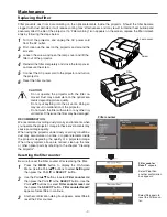
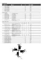
Mechanical Disassembly
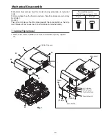
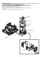
1. Remove 3 screws A(T3x8) to remove the exhaust fan assy.
2. Remove 2 screws B(M3x6) to remove the fan duct assy.
c
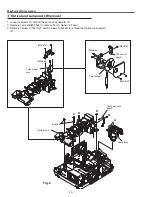
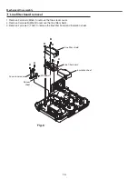
Fans (FN902, FN903, FN904) and SW901 removal
A
A A
B
B
Fig.3
(T3x32)x4
SW901
Lamp cover switch
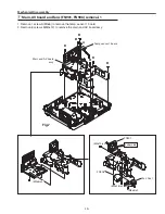
(T3x6)x1
(T3x8)x2
(T3x8)x1
(T3x12)x2
(T3x12)x2
(T3x8)x2
FN903
FN902
FN904
Air Filter
(T3x8)x1
Label side
Exhaust fan assy
Fan duct assy
Summary of Contents for PDG-DXL2000E
Page 47: ... 47 IC Block Diagrams LV49152V Audio output IC001 LC87F2G08A Sub micom IC4501 ...
Page 48: ... 48 IC Block Diagrams M62393 DAC IC7881 MR4010 Power switching IC631 ...
Page 49: ... 49 IC Block Diagrams PIC18F67J60 Network IC8301 NJW1156 Audio selector IC5101 ...
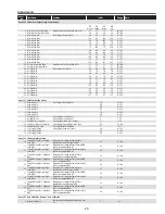
Page 82: ...Key No Part No Description Key No Part No Description Electrical Parts List 82 KV2 DXL2000E00 ...
Page 83: ...Key No Part No Description Key No Part No Description 83 Electrical Parts List KV2 DXL2000E00 ...
Page 84: ... KV2AC Apr 2011 DC 50 Printed in Japan SANYO Electric Co Ltd ...