


-22-
l
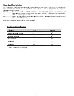
: Adjustment necessary
❍
: Check necessary
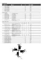
Adjustments after parts replacement
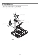
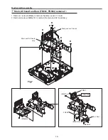
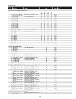
Disassembly / replaced parts
Optical unit
Color wheel
Power board
Main board
A
d
ju
st
m
en
ts
Fan voltage adjustment
l
l
Auto calibration adjustment [PC]
❍
Auto calibration adjustment [Component]
❍
Color Index Adjustment-1
l
l
Color Index Adjustment-2
l
Serial no. setting
l
Note on main board replacement
l
Memory IC replacement (IC1431)
Memory IC on the main board stores the user control value including lamp used time and product serial no. When
the main board is replaced with new one, the lamp used time and serial no. have a null value. To keep the lamp use
time and serial no., the memory IC should be replaced with the one on the previous main board.
l
Serial No. Setting
The serial no. displayed on the on-screen menu "Information" is stored in the memory IC on the main board. After
replacing the memory IC on the main board, if the serial no. on the "Information" menu is not displayed correctly,
use the serial no. setting tool to write the correct serial no. referring to the serial no. printed on the rating label. For
further details, refer to the operation manual of the serial no. setting tool [SST LITE v1.00]. The serial no. setting
tool is included in the service CD-RO below;
PrOJECtOr SErVICE tOOL CD-rOM v4.20
SErVICE CODE: 610 343 5596
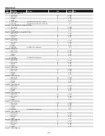
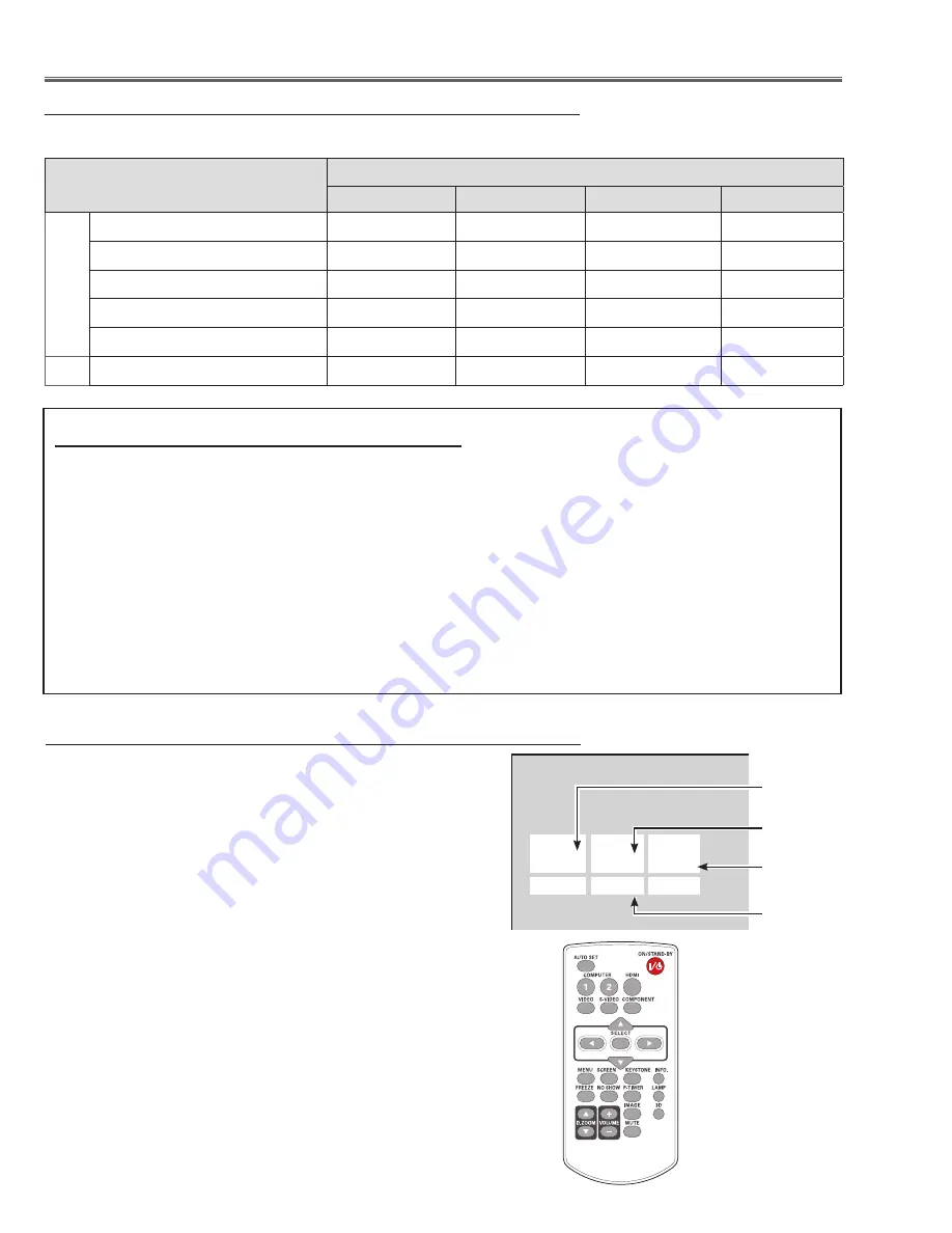
to enter the service mode
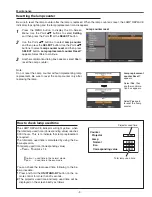
To enter the “Service Mode”, press and hold the
MENu
button
on
the remote control for more than 20 seconds. The service menu
appears on the screen as follows.
to adjust service data
Select the adjustment group no. by pressing the
MENu button
(increase) or
SELECt button
(decrease), and select the adjust-
ment item no. by pressing the pointer
e
or
d
button
, and change
the data value by pressing the
7
or
8
button
. Refer to the “Ser-
vice Adjustment Data Table” for further description of adjustment
group no., item no. and data value.
to exit the service mode
To exit the service mode, press the
ON/StAND-BY button.
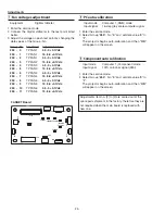
Service adjustment menu operation
Service Mode
Input
Input 1
Image
Standard
Group
No.
Data
0
0
32
Ver.
1.00
Data value
Item No.
Group No.
Firmware
Version No.
Adjustments
Summary of Contents for PDG-DXL2000E
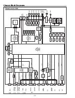
Page 47: ... 47 IC Block Diagrams LV49152V Audio output IC001 LC87F2G08A Sub micom IC4501 ...
Page 48: ... 48 IC Block Diagrams M62393 DAC IC7881 MR4010 Power switching IC631 ...
Page 49: ... 49 IC Block Diagrams PIC18F67J60 Network IC8301 NJW1156 Audio selector IC5101 ...
Page 82: ...Key No Part No Description Key No Part No Description Electrical Parts List 82 KV2 DXL2000E00 ...
Page 83: ...Key No Part No Description Key No Part No Description 83 Electrical Parts List KV2 DXL2000E00 ...
Page 84: ... KV2AC Apr 2011 DC 50 Printed in Japan SANYO Electric Co Ltd ...