Installation Work
1. Points regarding refrigerant pipe work
E-7
(3) Refrigerant pipe connection work
(1) Preparing and installing the tubing
•
Material: Phosphorous deoxidized copper seamless tubing (C1220T)
•
Tube size: Use the correct size according to Table 1.
Table 1
Tube size (mm)
φ
19.05
Outer dia.
φ
9.52
(C1220 O)
φ
12.7
(C1220 O)
φ
15.88
(C1220 O) (C1220 O) (C1220
1/2,H)
φ
22.2
(C1220
1/2,H)
φ
25.4
(C1220
1/2,H)
φ
28.58
(C1220
1/2,H)
φ
31.75
(C1220
1/2,H)
φ
38.1
(C1220
1/2,H)
Thickness
T0.8
T 0.8
T 1.0
T 1.2
T 1.0
T 1.0
T 1.0
T 1.0
T 1.1
T 1.35
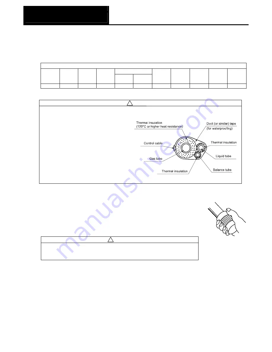
(2) Precautions regarding piping work
Caution
•
Apply thermal insulation to all tubing, including branch tubes. Make sure that there are no gaps or
openings in the thermal insulation that may allow moisture to enter. Use thermal insulation that can
withstand a minimum of 120°C for the gas
side (wide tube system), and a minimum of
80°C for the liquid side (narrow tube system).
Failure to do so can result in water leakage
and dripping condensation, leading to wall
discoloration, paddling, etc.
•
Use separate piping for the power cables
and the control cables. If the cables are
passed through the same pipes, the effects
of electrical noise and induction can cause
malfunctions.
(3) Select the gas pipe, liquid pope, blanches(separately sold), and make the necessary preparations for
installation.
•
After cutting the tube, be sure to remove all burrs and finish tubing ends to the
correct surface. (The same must be done for branch tubes (purchased
separately).)
•
When bending tubes, be sure the bend radius is at least 4 times the outer
diameter of the tube.
•
When cutting or bending tubes, be careful not to cause any pinching or blockage
of the tube.
Caution
Prevent foreign substances such as dirt or water from entering the tube by
sealing the end of the tubes with either a cap or with tape. Otherwise, this
can damage the devices and result in malfunction.
Figure 1
!
Figure 2
!
Summary of Contents for ECO G SGP-EGW190M2G2W
Page 3: ...A 1 System Configuration Contents 1 Type Configuration 1 Outdoor unit A 2 ...
Page 9: ...Outdoor Unit 3 External Dimensions B 5 ...
Page 10: ...Outdoor Unit 4 Wiring Diagram B 9 ...
Page 13: ...Outdoor Unit 6 Operating Sound Level Characteristics B 9 1 Standard Mode ...
Page 14: ...Outdoor Unit 6 Operating Sound Level Characteristics B 10 2 Quiet Mode ...
Page 17: ...Control 1 System Block Diagram C 2C 2 ...
Page 18: ...Control Related 2 Remote Control Warning List C 3 ...
Page 19: ...Control Related 2 Remote Control Warning List C 4 ...
Page 20: ...Control Related 2 Remote Control Warning List C 5 ...
Page 41: ...Installation Work 1 Points regarding refrigerant pipe work E 3 APR P680BG ...
Page 42: ...Installation Work 1 Points regarding refrigerant pipe work E 4 APR P1350BG ...
Page 43: ...Installation Work 1 Points regarding refrigerant pipe work E 5 APR CHP680BG APR CHP1350BG ...
Page 51: ...Installation Work 2 Points regarding electrical work outdoor unit E 13 ...
Page 52: ...Installation Work 3 Outdoor unit installation work E 14 ...
Page 53: ...Installation Work 3 Outdoor unit installation work E 15 ...
Page 54: ...Installation Work 3 Outdoor unit installation work E 16 ...
Page 55: ...Installation Work 3 Outdoor unit installation work E 17 ...
Page 56: ...Installation Work 3 Outdoor unit installation work E 18 ...
Page 57: ...Installation Work 3 Outdoor unit installation work E 19 ...
Page 58: ...Installation Work 3 Outdoor unit installation work E 20 ...
Page 59: ...Installation Work 3 Outdoor unit installation work E 21 ...
Page 60: ...Installation Work 3 Outdoor unit installation work E 22 ...
Page 61: ...Installation Work 3 Outdoor unit installation work E 23 ...
Page 62: ...Installation Work 3 Outdoor unit installation work E 24 ...
Page 63: ...Installation Work 3 Outdoor unit installation work E 25 ...
Page 64: ...Installation Work 3 Outdoor unit installation work E 26 ...
Page 65: ...Installation Work 3 Outdoor unit installation work E 27 ...
Page 66: ...Installation Work 3 Outdoor unit installation work E 28 ...
Page 67: ...Installation Work 3 Outdoor unit installation work E 29 ...
Page 68: ...Installation Work 3 Outdoor unit installation work E 30 ...
Page 69: ...Installation Work 3 Outdoor unit installation work E 31 ...
Page 70: ...Installation Work 3 Outdoor unit installation work E 32 ...
Page 71: ...Installation Work 3 Outdoor unit installation work E 33 ...


