-E8-
Y
R
L
P
B
P
R
AUDIO OUT
VIDEO OUT
COMPONENT VIDEO OUT
OPT.
DIGITAL
OUT
VIDEO OUT
SELECT
S
COMPONENT
S-VIDEO OUT
COMPONENT VIDEO INPUT
AUDIO INPUT
Y
P
B
R
L
P
R
+
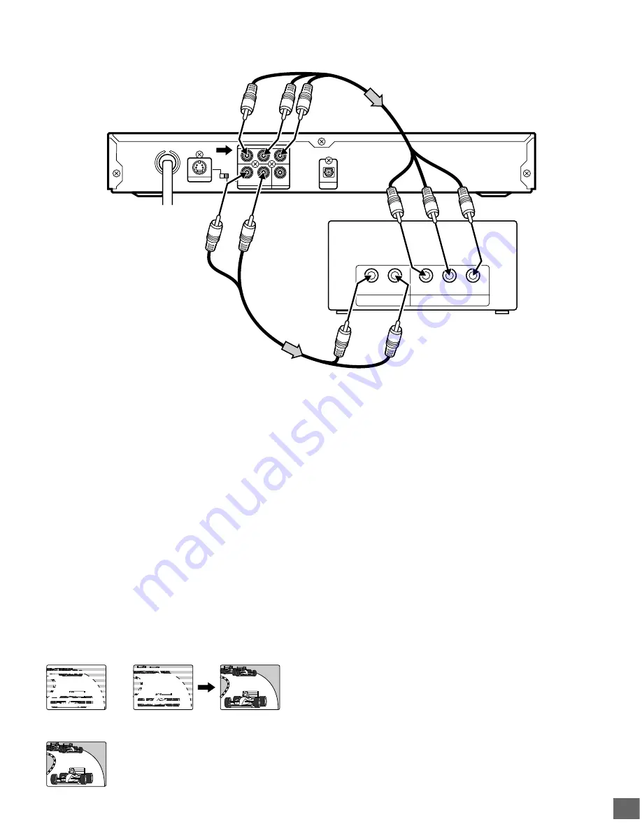
1. Connect the DVD video player to the component video input
jacks of the TV. (The VIDEO OUT or S-VIDEO OUT jack
connection is not necessary.)
2. Set the VIDEO OUT SELECT switch to the COMPONENT
position.
3. You also need to connect the left and right audio cables (not
supplied) to the AUDIO OUT jacks of DVD video player and
the Audio input jacks of the TV.
4. Set the DVD video player to the PROGRESSIVE position.
See page E13.
*Please consult your local audio/video dealer.
(White) L
To AUDIO OUT jacks
DVD video player
*Audio cable (not supplied)
(Red) R
To audio
input jacks
(White) L
(Red) R
*Component video cable (not supplied)
Green
Red
Blue
Green
Red
Blue
Progressive Scanning
While interlaced scanning produces one frame of video in two
fields, progressive scanning creates one frame in one field.
Conventional interlaced scanning constitutes one second with
30 frames (60 fields), but progressive scanning constitutes it with
60 frames from scratch. Progressive scanning can reproduce
sharper picture with high resolution for still image or other picture
containing long texts or horizontal lines.
This model has compliance with 525p (progressive) system.
TV with progressive-scan capability
Connecting to a TV with Progressive-scan Capability (Example 2)
Notes:
•
Please refer to your TV instruction manual.
•
When you connect the DVD video player to your TV, be sure
to turn off the power and disconnect both units from the wall
outlet until all the connections have been made.
•
Do not connect the DVD video player to a VCR directly. The
playback picture will be distorted because DVD video discs
are copy protected.
To AC 120V, 60Hz
Your TV must be capable of handling progressive scanning and have component video input capability.
Interlaced scanning
Progressive scanning
To COMPONENT VIDEO
OUT jacks
To COMPONENT VIDEO
INPUT jacks


