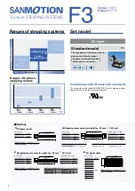
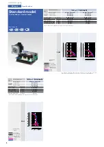


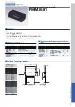


HIC for stepping motor
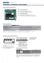
Specifications
Item
Symbol
Condition
Rating
Unit
MIN.
Standard
MAX.
V
CC2
source current
I
CCO
Enable =
“
L
”
−
6.1
12
mA
Effective output current
I
oe
Each phase R/L = 2
Ω
/6mH
2W2-3phase energization
0.92
1.03
1.14
A
rms
FET diode forward voltage
V
df
If = 1A
(
RL=23
Ω)
−
1.0
1.6
V
Output saturation voltage
V
sat
RL = 23
Ω
−
0.30
0.40
V
Output leak current
I
OL
RL = 23
Ω
−
−
0.1
mA
“
H
”
level input voltage
V
IH
Pins 11 to 18
4.0
−
−
V
“
L
”
level input voltage
V
IL
Pins 11 to 18
−
−
1.0
V
Input current
I
IL
Pins 11 to 18 = GND level
Pull-up resistance : 20k
Ω
115
250
550
μ
A
V
ref
input voltage
V
rH
Pin 10
0
−
V
CC2
/ 2
V
V
ref
input current
I
r
Pin 10 = 2.5 V
Internal resistance : 4k
Ω
440
625
810
μ
A
“
H
”
level MOI output voltage
V
OH
Pins 20-19 = 820k
Ω
2.5
−
−
V
“
L
”
level MOI output voltage
V
OL
Pins 21-20 = 1.6k
Ω
−
−
0.4
V
PWM frequency
F
C
−
23
31
39
kHz
C1
C2
C3
C4
470
μ
F
6.8
μ
F
0.1
μ
F
10
μ
F
■
Electrical characteristics
(
Tc=25
°
, V
CC1
=24 V, V
CC2
=5 V
)
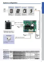
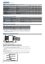
■
Function of each terminal
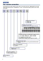
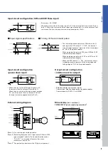
■
Example of Application Circuit
Recommended circuit part constants
●
For the R1 and R2 constants, determine the V
ref
voltage according to the following equation.
V
ref
(
V
)
= motor current adjustment value
(
A/phase
)
x 0.41
Notice that 100
Ω
is recommended for R2 due to the configuration of the internal circuit of the
PMM3501.
●
Place the GND side of the source by-pass capacitor of V
CC1
(
C1
)
as close to pins 27 and 28 as
possible to reduce noise.
●
Set
“
RESET
”
to High 10
μ
secs after
“
+5 V
”
rises above
“
+4.5 V
”
, as shown in Fig 1. When turning
on the power with
“
ENABLE
”
set to Low, set
“
RESET
”
to High after
“
+24 V
”
rises completely.
Function of each terminal
Function
Input condition for operation
V
ref
Motor current setting input
−
Clock
Pulse input for motor drive
Mode C =
“
H
”
: Rising edge operation
Mode C =
“
L
”
: Rising edge and falling edge operation
Hold
Pause input
Hold =
“
L
”
level
CW/CCW
Motor rotational direction setting input
“
H
”
level = CW rotation
“
L
”
level = CCW rotation
Enable
Power off input
Enable =
“
L
”
level
Reset
System reset
Reset =
“
L
”
level
MOI
Rotation monitor output
H level output once for each phase current period
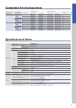
■
Energization mode table
Input
Condition energization mode 1 step angle
(
degree
)
Basic step division
Mode A
Mode B
Mode C
L
L
H
2EX
1.2
1
L
H
H
2-3EX
0.6
2
H
L
H
W2-3EX
0.3
4
H
H
H
2W2-3EX
0.15
8
H
H
L
4W2-3EX
0.075
16
• When Mode C =
“
L
”
, 1 step operation is performed for each rising edge and falling edge of the
Clock pulse. If the duty ratio of the drive pulse moves out of the adjustment significantly by 50
%, operation becomes unstable.
3-phase STEPPING SYSTEMS