background image

Bedienungsanleitung / User Manual SPVM-20AC / SPVM-26AC / SPVM-32AC


_________________________________________________________________________________ 


- 51 - 


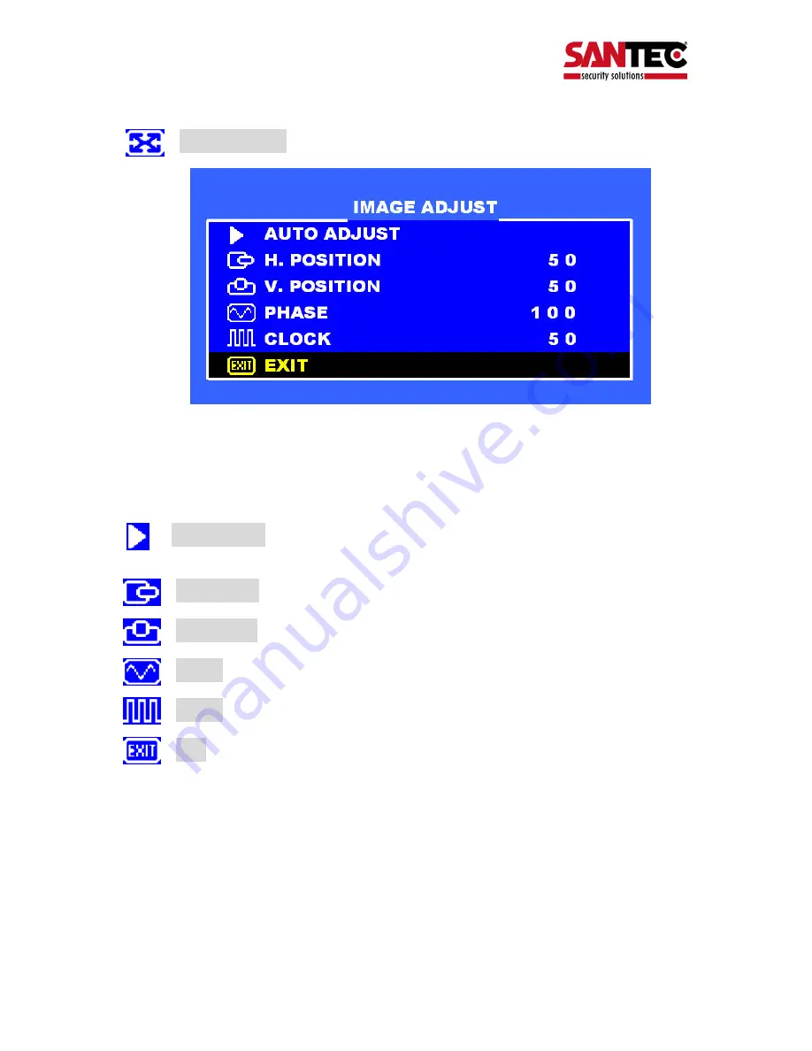
 IMAGE  ADJUST


 Press 

UP / DOWN

 buttons to select an icon. 

 Press 

MENU

 button to select adjust item. 

 Press 

Left / Right

 buttons to adjust the value. 

 Press 

MENU

 button to return. 


   AUTO ADJUST

Press 

MENU 

buttons to auto adjust the H. Position, 

V. Position, Phase, Clock. 


 H. POSITION

Adjust the horizontal position value. 


 V. POSITION

Adjust the vertical position value. 


 PHASE

Adjust the phase value. 


 CLOCK

Adjust the clock value. 


 EXIT

Press 

MENU

 button to return to the main menu. 


Summary of Contents for SPVM-20AC

Page 1: ...Version 1 0k f 1009 dt en A5 BEDIENUNGSANLEITUNG USER MANUAL DEUTSCH ENGLISH Public View Monitor PVM Modelle Models SPVM 20AC SPVM 26AC SPVM 32AC...

Page 2: ...video com SANTEC Service Hotline 49 0 900 1 72 68 32 49 0 900 1 SANTEC 0 89 Minute aus dem Fest netz der Deutschen Telekom AG support santec video com Impressum Das Copyright dieser Bedienungsanleitu...

Page 3: ...l rights reserved This publication may not be reproduced stored in a retrieval system or transmitted in any form or by any means electronic mechanical photocopying recording or otherwise without the w...

Page 4: ...SPVM 20AC 10 4 2 OSD Men f r SPVM 26AC und SPVM 32AC 13 5 Einstellung der eingebauten WDR Kamera 23 6 Rechtliches 35 7 Ausfallzeit 35 8 Technische Spezifikationen 36 9 Anhang Abmessungen 38 ENGLISH TA...

Page 5: ...st auf unbedingt zu beachtende Betriebs und Wartungsanweisungen hin CE Richtlinien Vorsicht nderungen und Modifizierungen die nicht ausdr cklich durch die zust ndige Genehmigungsbeh rde genehmigt word...

Page 6: ...lt werden Sorgen Sie daf r dass das Ger t nicht berhitzt wird Verwenden Sie nur die empfohlene Betriebsspannungsversorgung Wenn Sie nicht sicher sind ob die am Installationsort vorhandene Stromversorg...

Page 7: ...hlen Dieser Nachzieheffekt ist kein Fehler sondern eine Eigenart der Halbleiter CCD s wenn dieser einer starken Lichtquelle direkt ausgesetzt wird Bitte beachten Sie im Fall der Entsorgung unbrauchbar...

Page 8: ...t ebenfalls zur Verf gung so dass dieses Ger t einfach zu bedienen ist 2 Funktionale Spezifikationen Betriebsspannung Das Ger t wird mit folgender Spannung versorgt AC Eingangsspannung 100 240VAC 60 5...

Page 9: ...ionstaste inklusive Fernbedienung und Front Panel CAM CVBS S Video PC Tasten f r die unterschiedlichen Kan le SPVM 20AC unterst tzt die S Video Funktion nicht Menu OSD Men UP Down Left Right Dr cken S...

Page 10: ...stellen Dr cken Sie die MENU Taste um das OSD Men zu verlassen VOLUME Lautst rke Dr cken Sie die Taste um diese Funktion auszuw hlen Dr cken Sie die Taste um die Lautst rke einzustellen Dr cken Sie di...

Page 11: ...MENU Taste um ins Hauptmen zur ckzukehren COLOR ADJUST Stellen Sie die Farbtemperatur des Monitorsauf den Wert 9300 K oder 6500 K ein oder w hlen Sie den USER MODE 6500 Dr cken Sie die Taste um die Fa...

Page 12: ...te nur f r CAM1 und CAM2 MUX OUTPUT EXT CVBS Dr cken Sie die Taste um die MUX OUTPUT Quelle einzustellen SETUP MENU LANGUAGE Sprache Dr cken Sie die MENU Taste und die Taste um die Sprache auszuw hlen...

Page 13: ...32AC Hot key Fernbedienung BRIGHTNESS Helligkeit Dr cken Sie die UP Taste um diese Funktion auszuw hlen Dr cken Sie die Left Right Taste um die Helligkeit einzustellen CONTRAST Kontrast Dr cken Sie d...

Page 14: ...us Dr cken Sie die UP DOWN Taste um einen Punkt auszuw hlen Dr cken Sie die MENU Taste um die Werte im Untermen zu ndern MAIN ADJUST Dr cken Sie die UP DOWN Taste um einen Punkt anzuw hlen Dr cken Sie...

Page 15: ...ins Hauptmen zur ckzukehren COLOR ADJUST Stellen Sie die Farbtemperatur des Monitors auf den Wert 9300 K oder 6500 K ein oder w hlen Sie den USER MODE Dr cken Sie die UP DOWN Taste um einen Punkt anz...

Page 16: ...Punkt auszuw hlen Dr cken Sie die Left Right Taste um den Wert einzustellen Dr cken Sie die MENU Taste um ins Men zur ckzukehren AUTO ADJUST Dr cken Sie die MENU Taste um folgende Werte einzustellen...

Page 17: ...um einen Punkt auszuw hlen Dr cken Sie die Left Right Taste um den Wert einzustellen Dr cken Sie die MENU Taste um ins Men zur ckzukehren LANGUAGE Sprache Dr cken Sie die MENU Taste um die Sprache au...

Page 18: ...Punkt auszuw hlen Dr cken Sie die Left Right Taste um den Wert einzustellen Audio1 oder Mute Dr cken Sie die MENU Taste um ins Men zur ckzukehren CAMERA Einstellung der Audio Eingangsquelle beim CAME...

Page 19: ...VM 26AC SPVM 32AC _________________________________________________________________________________ 19 Video Modus Dr cken Sie die Up Down Taste um einen Punkt auszuw hlen Dr cken Sie die MENU Taste u...

Page 20: ...kzukehren VIVID MODE Einstellung des VIVID MODE 0 3 und USER 0 NORMAL 1 TEXT 2 PHOTO 3 MOVIE BRIGHTNESS Helligkeit Einstellung der Helligkeit CONTRAST Kontrast Einstellung der Helligkeit SHARPNESS Sch...

Page 21: ...USER MODE Dr cken Sie die UP DOWN Taste um einen Punkt anzuw hlen Dr cken Sie die MENU Taste um einen Punkt auszuw hlen Dr cken Sie die Left Right Taste um den Wert einzustellen Dr cken Sie die MENU T...

Page 22: ...cken Sie die UP DOWN Taste um einen Punkt anzuw hlen Dr cken Sie die MENU Taste um einen Punkt auszuw hlen Dr cken Sie die Left Right Taste um den Wert einzustellen Dr cken Sie die MENU Taste um ins M...

Page 23: ...l ca 470 K Synchronisation Intern LineLock 3 3V VD Puls Eingang Min Beleuchtung 0 01 Lux F1 2 20 IRE AGC 30 dB Farbe 0 0014 Lux F1 2 40 IRE Sens up 32x Objektiv und Blickwinkel 3 9 mm F1 1 2 2 1 116 5...

Page 24: ...1 12V 1 CLK 1 DMP 1 ENT 1 nicht belegt ausschlie lich f r Hersteller 2 ICR AUTO EXT 2 GND 2 D0 2 DMP 2 PRI 2 3 V REV OFF ON 3 VBS 3 D1 3 DRV 3 UP 3 4 H REV OFF ON 4 GND 4 D2 4 GND 4 DOWN 4 5 BLC OFF...

Page 25: ...und den elektronischen Verschluss einstellen Sie k nnen w hlen zwischen SWDR ALC AES SWDR SWDR Modus kann auf ON OFF gestellt werden Im ON Modus kann der SWDR Level eingestellt werden ALC Im ALC Modus...

Page 26: ...ellungen vorgenommen haben best tigen Sie die Eingabe mit ENT Anschlie end dr cken Sie die PRI Taste um ins Hauptmen zur ckzukehren 5 4 4 BLC Gegenlichtkontrolle Hier k nnen Sie die Gegenlichtkontroll...

Page 27: ...hite Balance Wei abgleich ATW Auto Trace White Balance Bewegen Sie den Pfeil von ATW zu AWB um die momentane Farbtemperatur festzusetzen GAIN Die Gain Rate kann f r R Y und B Y separat eingestellt wer...

Page 28: ...filter ist auf ein externes Signal ausgerichtet Nachdem Sie Ihre Einstellungen vorgenommen haben best tigen Sie die Eingabe mit ENT Anschlie end dr cken Sie die PRI Taste um ins Hauptmen zur ckzukehre...

Page 29: ...len OFF Die Bewegungserkennung ist ausgeschaltet ON Die Bewegungserkennung ist eingeschaltet AREA Hier k nnen Sie den Bewegungserkennungsbereich festlegen Mit den UP und DOWN Tasten bewegen Sie den gr...

Page 30: ...ur ckzukehren 5 4 12 Maskierungsbereich Hier k nnen Sie den Maskierungsbereich seine Gr e und Position festlegen NO W hlen Sie eine Bereichsnummer aus 1 4 OFF Der Maskierungsbereich ist ausgeschaltet...

Page 31: ...ausgeschaltet werden ON OFF Nachdem Sie Ihre Einstellungen vorgenommen haben best tigen Sie die Eingabe mit ENT Anschlie end dr cken Sie die PRI Taste um ins Hauptmen zur ckzukehren 5 4 14 Cross line...

Page 32: ...ie Ihre Einstellungen vorgenommen haben best tigen Sie die Eingabe mit ENT Anschlie end dr cken Sie die PRI Taste um ins Hauptmen zur ckzukehren 5 4 16 Digitales Output Format Hier k nnen Sie das digi...

Page 33: ...ION Definieren Sie die Position des Titels OFF zeigt den Titel nicht an Mit UP oder DOWN l sst sich die Position verschieben Nachdem Sie Ihre Einstellungen vorgenommen haben best tigen Sie die Eingabe...

Page 34: ...ie die Presets oder die Phase LineLock einstellen PRESET Ein ausschalten des Presets ID RS 485 Anschluss W hlen Sie die ID Nummer PHASE Ein ausschalten des LineLock Modus Im ON Modus kann die LineLock...

Page 35: ...3rd edition 6 2 EMI EMS Bestimmungen Dieses Ger t entspricht folgenden EMI EMS Bestimmungen FCC Compliance FCC Rules and Regulations Part 15 subpart B Class A CE COMPLIANCE EN55022 1998 class A EN5502...

Page 36: ...66 x 768 Farben 16 2 Mio 6bit FRC 16 7 Mio 16 7 Mio Response Time 16 ms 6 5 ms GTG 6 5 ms GTG Eingang Ausgang Terminals Externer Video Eingang Ausgang MUX Video Ausgang W hle Ext CVBS Cam1 Ausgang mit...

Page 37: ...sch Betriebstemperatur 0 bis 40 C Lagertemperatur 20 bis 60 C Richtlinien FCC CE RoHS Interne Kamera Spezifikationen MODELL Beschreibung WDR Kamera Video I O PAL Bildsensor 1 3 I L CCD Image Sensor Bi...

Page 38: ...SPVM 20AC SPVM 26AC SPVM 32AC _________________________________________________________________________________ 38 9 Anhang Abmessungen SPVM 26AC f r SPVM 20AC und SPVM 32AC siehe Spezifikationsliste...

Page 39: ...Bedienungsanleitung User Manual SPVM 20AC SPVM 26AC SPVM 32AC _________________________________________________________________________________ 39...

Page 40: ...ct s enclosure that may be of sufficient magnitude to constitute a risk of electric shock to a person Warning This symbol is intended to alert the user to the presence of important operating and maint...

Page 41: ...e unit should only be operated from the type of power source indicated on the marking label If you are not sure of the type of power supplied at the installation location please contact your local dea...

Page 42: ...an object with a high degree of luminance Bright vertical or horizontal lines can result in a distortion outshine of the entire image on the monitor This artifact is not an error but a particularity...

Page 43: ...video pictures A user friendly OSD menu is also provided to make this system easy to operate 2 Functional specifications Power supply The power supply specifications are as follows AC power input 100...

Page 44: ...remote control and front panel CAM CVBS S Video PC Channel button SPVM 20AC does not support the S Video function Menu OSD menu function UP Down Left Right Press these four buttons to move the cursor...

Page 45: ...d press buttons to adjust the brightness value the press MENU button to exit OSD menu VOLUME Press button to select the function and press buttons to adjust the volume value the press MENU button to e...

Page 46: ...EXIT Press MENU button to return to the main menu COLOR ADJUST Set the colour temperature of the LCD monitor for the CIE coordinate 9300 K or 6500 K or USER MODE 6500 Press buttons to adjust the colo...

Page 47: ...IMAGE Press buttons to adjust only for CAM1and CAM2 MUX OUTPUT EXT CVBS Press buttons to adjust MUX OUTPUT source by extend cable SETUP MENU LANGUAGE Press MENU buttons and buttons to select the langu...

Page 48: ...s MENU button to return to the main menu 4 2 OSD menu for SPVM 26AC and SPVM 32AC Hot key Remote control BRIGHTNESS Press UP button to select the function and press Left Right buttons to adjust the br...

Page 49: ..._________________________________ 49 PC mode Press UP DOWN buttons to select an icon then press MENU button to change the values in the sub menu MAIN ADJUST Press UP DOWN buttons to select an icon Pre...

Page 50: ...lue EXIT Press MENU button to return to the main menu COLOR ADJUST Set the colour temperature of the LCD monitor for the CIE coordinate 9300 K or 6500 K or USER MODE Press UP DOWN buttons to select an...

Page 51: ...Press MENU button to select adjust item Press Left Right buttons to adjust the value Press MENU button to return AUTO ADJUST Press MENU buttons to auto adjust the H Position V Position Phase Clock H...

Page 52: ...select an icon Press MENU button to select adjust item Press Left Right buttons to adjust the value Press MENU button to return LANGUAGE Press MENU buttons to change the language OSD TIMEOUT Adjust t...

Page 53: ...icon Press MENU button to select adjust item Press Left Right buttons to adjust the value AUDIO 1 or Mute Press MENU button to return CAMERA Adjust the audio input source in CAMERA channel CVBS Adjust...

Page 54: ...M 20AC SPVM 26AC SPVM 32AC _________________________________________________________________________________ 54 Video mode Press Up Down buttons to select an icon then press MENU button to change the...

Page 55: ...adjust the value Press MENU button to return VIVID MODE Adjust the VIVID MODE 0 3 and USER 0 NORMAL 1 TEXT 2 PHOTO 3 MOVIE BRIGHTNESS Adjust the brightness value CONTRAST Adjust the contrast value SH...

Page 56: ...the CIE coordinate 9300 K or 6500 K or USER MODE Press Up Down buttons to select an icon Press MENU button to select adjust item Press Left Right buttons to adjust the value Press MENU button to retur...

Page 57: ...CAN SETTING Press MENU button to select the sub menu Press Up Down buttons to select an icon Press MENU button to enter Press Left Right buttons to select item Press MENU button to return OVERSCAN Adj...

Page 58: ...illumination 0 01 lux F1 2 20 IRE AGC 30 dB colour 0 0014 lux F1 2 40 IRE Sens up 32x Lens and angle of view 3 9mm F1 1 2 2 1 116 5 40 2 Resolution 540 TVL White balance Mode ATW AWC Range 3200 10000...

Page 59: ...1 CLK 1 DMP 1 ENT 1 for manufacturer purposes only not released 2 ICR AUTO EXT 2 GND 2 D0 2 DMP 2 PRI 2 3 V REV OFF ON 3 VBS 3 D1 3 DRV 3 UP 3 4 H REV OFF ON 4 GND 4 D2 4 GND 4 DOWN 4 5 BLC OFF ON 5...

Page 60: ...5 4 2 Iris This is used to control the iris shutter speed of the lens It included 3 items SWDR ALC AES SWDR SWDR mode ON OFF selection At ON mode the SWDR level can be adjusted ALC ALC is used to sele...

Page 61: ...or OFF 9 adjustable steps at AUTO mode After the setting has been completed press ENT to save the adjustments After that press the PRI key to go back to the main menu page 5 4 4 BLC Backlight compensa...

Page 62: ...ally to monochrome image WB White balance control ATW Auto Trace White Balance Move the arrow from ATW to AWB and it will lock the current colour temperature GAIN The gain rate of R Y and B Y can be a...

Page 63: ...sec EXT If you select this mode the IR cut filter is set to external signal After the setting has been completed press ENT to save the adjustments After that press the PRI key to go back to the main...

Page 64: ...e 5 4 10 Motion detection This is used to select the montion dection function OFF Motion detection function is OFF ON Motion detect function is ON AREA At the this mode you can select the motion detec...

Page 65: ...o back to the main menu page 5 4 12 Mask This is used to select the mask area size its position and the mask area display ON or OFF NO Select themask area number 1 4 OFF The mask area display is switc...

Page 66: ...can be displayed to ON OFF After the setting has been completed press ENT to save the adjustments After that press the PRI key to go back to the main menu page 5 4 14 Cross line Freeze This is used to...

Page 67: ...ter the setting has been completed press ENT to save the adjustments After that press the PRI key to go back to the main menu page 5 4 16 Digital output This is used to select the digital output forma...

Page 68: ...e character to the selected position POSITION Set the title display to OFF or move its position by using UP or DOWN After the setting has been completed press ENT to save the adjustments After that pr...

Page 69: ...is used to set the Preset to ON OFF or to set the Phase LineLock to ON OFF PRESET Set the Preset to ON OFF mode ID RS 485 connection select the ID number PHASE Set the LineLock mode to ON OFF At ON m...

Page 70: ...D IEC 60950 1999 3rd edition 6 2 EMI EMS emission approvals This series design shall meet following EMI EMS specifications FCC Compliance FCC Rules and Regulations Part 15 subpart B Class A CE COMPLIA...

Page 71: ...1366 x 768 Display color 16 2M 6bit FRC 16 7M 16 7M Response time 16ms 6 5ms GTG 6 5ms GTG Input Output Terminals Ext Video In Out MUX Video Output Select Ext CVBS Cam1 out with BNC x 1 External CVBS...

Page 72: ...tuguese Operating temperature 0 to 40 C Storage temperature 20 to 60 C Regulation FCC CE RoHS Internal Camera specification MODEL DESCRIPTION WDR Camera Video I O select PAL Image device 1 3 I L CCD I...

Page 73: ...anual SPVM 20AC SPVM 26AC SPVM 32AC _________________________________________________________________________________ 73 9 Appendix Dimensions SPVM 26AC for SPVM 20AC and SPVM 32AC see specification t...

Page 74: ...Bedienungsanleitung User Manual SPVM 20AC SPVM 26AC SPVM 32AC _________________________________________________________________________________ 74 Notizen Notes...

Page 75: ...Bedienungsanleitung User Manual SPVM 20AC SPVM 26AC SPVM 32AC _________________________________________________________________________________ 75 Notizen Notes...

Page 76: ...__________________________________________________________________________ www santec video com Ihr Fachh ndler Your local distributor...

Reviews: