


S&C Instruction Sheet 653-506
13
NOTICE
The battery bay in Figure 3 on page 12 shows the PCM section on the right side and the
battery module on the left side of the bay . These are right-hand battery bays .
At the rear of the enclosure, the PCM section and battery module configurations are
reversed, where the PCM is on the left side and the battery module is on the right side of
the bay . These are left-hand battery bays .
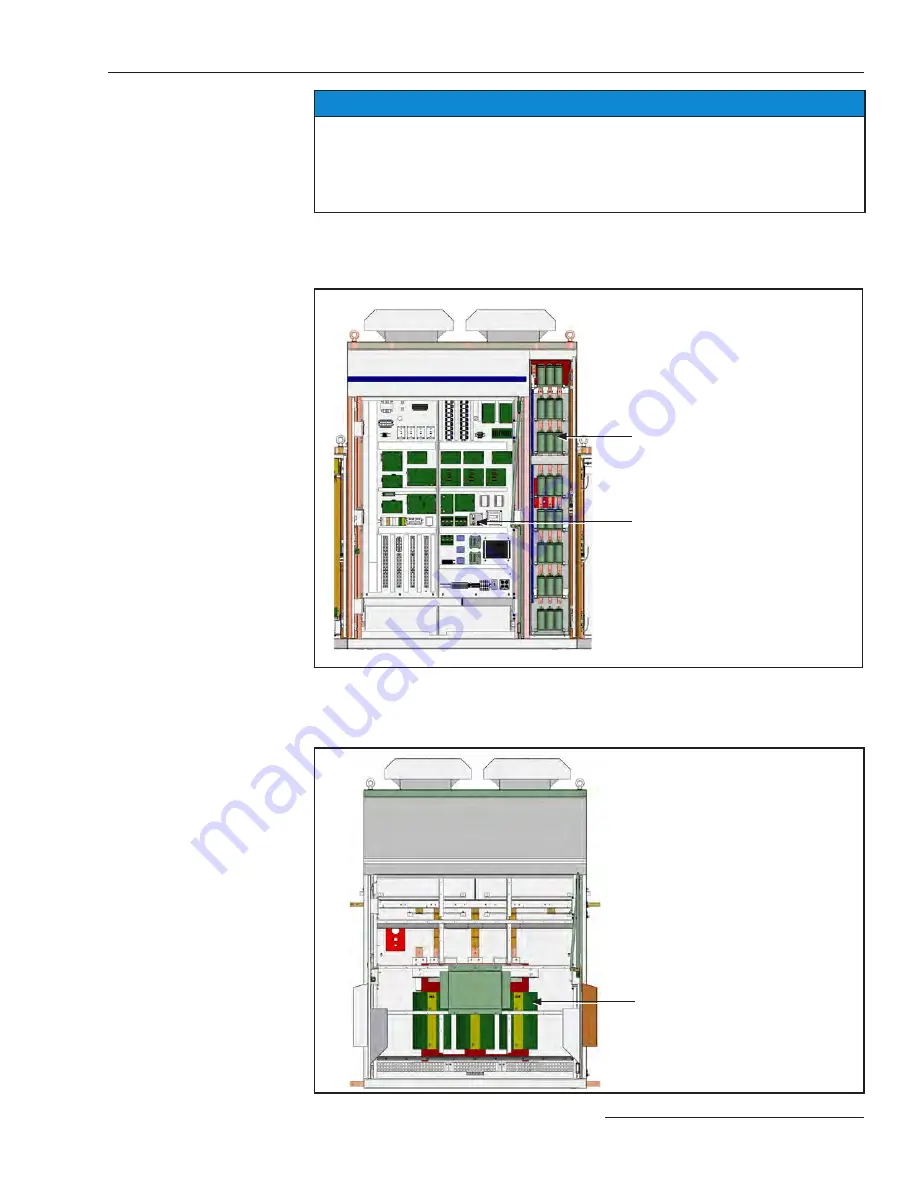
Control bay
- The control bay houses the control system and ac filter capacitor section.
Inside of the control bay is a control panel which has a RESET pushbutton, an HVAC TEST
pushbutton, a CPC connector, and an ENABLE/DISABLE switch See Figure 4 for a view of
the control bay.
Ac filter capacitor section
Control panel
Figure 4. View of the control bay (with the doors open).
Transformer bay
- The transformer bay, which is located at the rear of the enclosure, houses
the isolation transformer used to match the voltage of the critical load once the energy from
the system batteries is converted to ac. See Figure 5 for a view of the transformer bay.
Transformer
Figure 5. View of the transformer bay (with the door open).
Components and Controls