background image

S&C Instruction Sheet 766-527LD    13

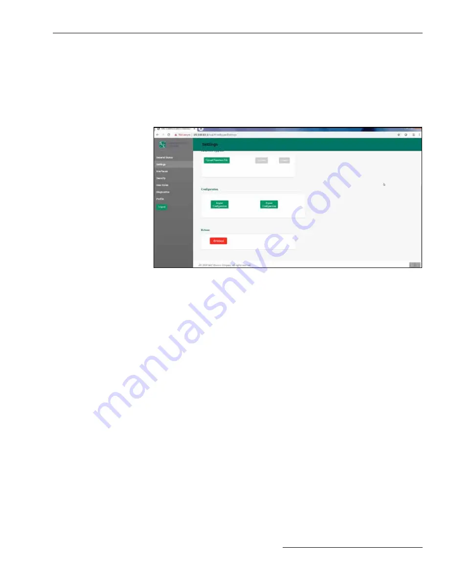
Figure 10. The Configuration and Reboot panels on the 

Settings

 screen.

Import Configuration

Follow these steps to complete the 

Import Configuration

 command:

STEP  1.  

In the Configuration panel, click on the 

Import Configuration

 button. A Web 

User Interface (WUI) dialogue box opens.

STEP  2.  

Click on the 

Choose File

 button, which invokes a Windows file navigation box.

STEP  3.  

Navigate to the file.

STEP  4.  

Highlight the file and click on the 

Open

 button. The highlighted file will be 

identified in the WUI dialogue box.

STEP  5.  

Click on the 

Import

 button.

STEP  6.  

Click on the 

Save

 button.

Export Configuration

Follow these steps to complete the 

Export Configuration

 command:

STEP  1.  

In the Configuration panel, click on the 

Export Configuration

 button. A WUI 

dialogue box opens with a suggested filename for the exported configuration. 
The default name is “textFile” but it can be changed.

STEP  2.  

Click on the 

Export

 button.

STEP  3.  

Wait a few seconds for the exported file to open in your browser. The file will be 
stored in the Downloads folder.

Reboot

The red colored 

Reboot

 button enables the user to restart the Wi-Fi/GPS Unit. When 

selected, a dialogue box appears for confirmation of the 

Reboot

 command. After 

the 

OK

 button is clicked, the user interface shows an Unavailable dialog box. The 

entire reboot process requires approximately 5 minutes before communication to the  
Wi-Fi/GPS Unit is re-established. When the reboot is complete, the user interface will 
automatically load the 

Login

 screen.

Wi-Fi Administration

Configuration Files

The Wi-Fi/GPS Unit can perform bulk imports and exports of specific configuration data 
parameters. The same XML file format is used for both import and export functions. This 
allows a user to configure settings in one device, export those settings into an XML file 
(the extension is “.json”), and import the same settings into another unit. Clicking on the 

Import Configuration

 or 

Export Configuration

 button invokes a series of dialogue 

boxes allowing navigation on a PC to a configuration file for import or saving a file for 
export. See Figure 10.

Summary of Contents for 005-004701-01

Page 1: ...cation Technical Specification 6 Antenna Specification 7 Wi Fi Administration Connecting to the IntelliRupter Fault Interrupter 6800 Series Automatic Switch Control or IntelliCap 2000 Automatic Capaci...

Page 2: ...to Proper Application WARNING The equipment in this publication is only intended for a specific application The application must be within the ratings furnished for the equipment The standard warranty...

Page 3: ...the Wi Fi GPS Unit is contingent upon the installation configu ration and use of the control or software in accordance with S C s applicable instruction sheets This warranty does not apply to major c...

Page 4: ...dentifies important procedures or requirements that can result in product or property damage if instructions are not followed Following Safety Instructions If you do not understand any portion of this...

Page 5: ...lt interrupter base unless directed by S C Electric Company 6 ENERGIZED COMPONENTS Always consider all parts live until de energized tested and grounded The integrated power module IPM contains compon...

Page 6: ...assigned to LAN or WAN Ethernet IEEE 802 3 802 1Q VLANs IP protocols TCP UDP ARP DHCP client server ICMP Routing and failover IP pass through NAT NAPT with IP port forwarding and Ethernet bridging In...

Page 7: ...upplied or an equivalent replacement antenna Note Modifications to the device or use of unauthorized antennae as not expressly approved by S C Electric Company is the sole responsibility of the user c...

Page 8: ...en will open See Figure 1 Figure 1 The LinkStart Main screen STEP 2 Enter the serial number of the IntelliRupter fault interrupter and click on the Connect button See Figure 1 The Connect button chang...

Page 9: ...d green bar The vertical bar graph indicates signal strength of the Wi Fi connection See Figure 3 Figure 3 Successful connection to the IntelliRupter fault interrupter STEP 3 Open the Tools menu and c...

Page 10: ...your username and password and click on the Login button Authentication status is displayed The default username and password can be requested from S C by calling the Global Support and Monitoring Cen...

Page 11: ...Wi Fi Connected Clients panels The Identity panel contains six fields Name Software Version Serial Number App Version Platform Ver sion and Configuration Version The GPS panel contains five fields Sta...

Page 12: ...puter The firmware files are located in the S C Customer Portal at sandc com en support sc customer portal STEP 2 Click on the Upload Firmware File button in the Firmware Upgrade panel STEP 3 A Window...

Page 13: ...few seconds for the exported file to open in your browser The file will be stored in the Downloads folder Reboot The red colored Reboot button enables the user to restart the Wi Fi GPS Unit When selec...

Page 14: ...ul transport protocol When serial back haul networks are used or there is no WAN this panel will not require entries DHCP Client State On No fields require identification A DHCP request will be initia...

Page 15: ...n Method WPA2 Encryption WPA2 Passphrase Mode Channel Width and Transmit Power dBm See Figure 11 on page 14 The Wi Fi GPS Unit ships with a default Static IP address of 192 168 101 1 a Netmask equal t...

Page 16: ...he IntelliLink UDP Port number and the Radio Console TCP Port number The Wi Fi Session Timeout field determines the time after which the session will automatically terminate activity through the conne...

Page 17: ...t Port 2 This configuration setting can only be updated by the admin user and only after the admin user has changed the default password Web access via Ethernet Port 2 is also controlled by a DNP3 bin...

Page 18: ...nly available for use by the system administrator Admin Role and Additional Admin Role users User Roles Figure 16 The User Roles screen The permissions provided to each of the user roles is summarized...

Page 19: ...iagnostics screen initiates the retrieval of the Diagnostic and Event Log files See Figures 17 and 18 Figure 17 The Retrieve Full Diagnostics Logs button on the Diagnostics screen Diagnostics Figure 1...

Page 20: ...Figure 19 Profile Figure 19 The Profile screen A password entry requires at least one lowercase and one uppercase character When entries are complete click on the Apply button to save the new passwor...

Page 21: ...Unit See Figure 20 on page 22 STEP 5 Locate the Ethernet patch cord provided with the R3 Communication Module and plug one end into Ethernet 2 on the Wi Fi GPS Unit and the other into the Ethernet po...

Page 22: ...ace pinout Pin Function Description 1 NC No Connection 2 RX from Radio RS 232 Receive 3 TX to Radio RS 232 Transmit 4 NC No Connection 5 TX to Radio GND Signal Ground 6 NC No Connection 7 RTS to Radio...

Page 23: ...on 5 NC No Connection 6 RXD Receive 7 NC No Connection 8 NC No Connection The Wi Fi GPS Unit Ethernet ports use RJ 45 connectors with the pinout shown in Figure 22 They are auto sensing for assignment...

Page 24: ...lation instructions and consider removing the no collocation statement This device complies with Part 15 of the FCC Rules Operation is subject to the fol lowing two conditions 1 this device may not ca...

Page 25: ...et l imp dance requise pour chaque type d antenne Les types d antenne non inclus dans cette liste ou dont le gain est sup rieur au gain maximal indiqu sont strictement interdits pour l exploitation de...

Reviews: