6
2.4. Antenna Unit Mounting
Drill four bolt holes and cut out a cable access hole on the mounting site. (See
reference appendix.)
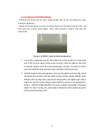
Position the base plate over the mounting holes and the cable access hole, and
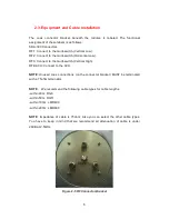
then align the radome base plate’s “Bow” label (shown in Figure 2-6) with the
ship’s bow.
Figure 2-6 “BOW” Label of the Radome Base
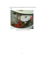
1. Connect the data/power and the RF cables from below decks to the base plate
with a 7/16” wrench, applying 30 pounds of torque. Check the label on both ends
of each RF cable to match its antenna base-plate connector. Do NOT use Teflon
gel on the cable fittings as it reduces signal strength at high frequencies.
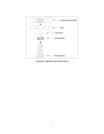
2. Install flat washers and spring washers and a mounting bolt to each mounting hole of
the radome base from the underside of the mounting surface. Apply Loctite 241 to the
threads of the mounting bolt up near the mounting surface and tighten each of the 4
bolts to 24 in-lb (21 kg-cm) of torque [finger tight, then about 1/4 turn tighter] with a
wrench. DO NOT OVER-TIGHTEN. You have to install mounting bolts of the proper
length. If a bolt is too long, the extra length of threaded rod that extends above the
radome base should be cut off.
Summary of Contents for SUPERTRACK SDA-390
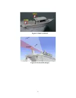
Page 7: ...3 Figure 2 2 Best Location II Figure 2 3 Antenna Blockages...
Page 11: ...7 Figure 2 7 Tighten the nuts from below...
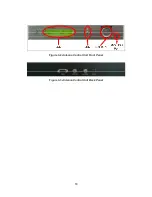
Page 22: ...18 Figure 3 2 Antenna Control Unit Front Panel Figure 3 3 Antenna Control Unit Back Panel...
Page 36: ...32 Connection Staus Display of LCD Figure 4 2 Connection Status SDA 390 with PC...
Page 39: ...35 Figure 4 5 Satellite List Update Step 2...
Page 48: ...44 C N Graph You can see the graph of C N on Antenna State Figure 4 13 C N Graph...
Page 55: ...51...


