background image


Installation and Operation Manual 

43 


Thank  you  for  purchasing  an  SAMYUNG  ENC  product.  This  product  has  been 
thoroughly checked and is covered by the 

Samyung ENC’s warranty

 for defects in 

materials and workmanship under normal use from the date of purchase. 
 
This warranty provides for the free repair or replacement of defective parts from our 
Samyung ENC authorized dealer. 
 
In  the  event  that  your  SAMYUNG  ENC  product  needs  service,  please  return  your 
SAMYUNG  ENC  product  at  your  expense  (shipping  and  insurance)  to  your  Samyung 
ENC distributor or SAMYUNG ENC authorized Service Centers. SAMYUNG ENC will, at 
its discretion, repair or replace any defective products or its components at no cost to 
you. This is your exclusive remedy for defective products 
 

Exclusions: 

are specifically excluded from warranty; 

1.


Consumable  items,  including,  but  not  limited  to:  fuses,  impellers,  impeller 
bearings, impeller shafts are specifically excluded from this warranty. . .   

2.


All costs associated with transducer replacement, other than the cost of the 
transducer itself. 

3.


Routine  system  checkouts,  alignment  and  calibration,  seatrials,  unless 
required by replacement of defective parts. 


Limited  warranty:

  SAMYUNG  ENC  will  not  be  responsible  for  equipment  that  has 

been damaged or rendered defective: 

1.


as a result of incorrect installation, misuse, accident, water damage, abuse 
or other external causes 

2.


by  modification  or  service  other  than  by  SAMYUNG  ENC  or  authorized 
distributors, authorized Service Centers. SAMYUNG ENC will not be liable in 
any event for any consequential or indirect loss or damage. Exceptions are 
expressly  set  out  in  this  warranty,  SAMYUNG  ENC  makes  no  other 
warranties,  express  or  implied,  including  any  implied  warranties  of 
merchantability  and  fitness  for  a  particular  purpose.  If  any  limitation  or 
exclusion of liability in this warranty is invalid and SAMYUNG ENC becomes 
liable  for  loss  or  damage  that  would  otherwise  have  been  excluded,  such 
liability  will  be  limited  to  the  total  amount  actually  paid  by  you  for  the 
product. 

3.


if  the  serial  number  label  on  the  unit  has  been  removed,  altered  or 
mutilated 


Summary of Contents for F560

Page 1: ......

Page 2: ...Installation and Operation Manual 2...

Page 3: ...ity to install and use the unit in a manner that will not cause accidents personal injury or property damage The user of this product is solely responsible for observing safe boating practices Global...

Page 4: ...o the current technology of the LCD display Avoid overheating which may cause loss of contrast and in extreme case a darkening of the screen Problems which occur from over heating are reversible when...

Page 5: ...eral Operation 3 1 Manual Auto Power on and off 17 3 2 Brightness night mode and Background 17 3 3 The page window 18 3 4 Sonar 19 3 4 1 Interpreting the display 19 3 4 2 Mode 19 3 4 3 Single and Dual...

Page 6: ...Digit size 31 4 2 5 Fish 31 4 2 6 Advance Settings 31 4 2 7 Restore default 31 4 3 Memory Settings 32 4 3 1 Screen snap shot 32 4 4 AIS Settings 32 4 4 1 Alarm option 32 4 4 2 Restore default 32 4 5 A...

Page 7: ...eration Manual 7 5 INSTALLATION 5 1 Options and Accessories 36 5 2 Connections 37 5 3 Power data cable 37 5 4 Alarm 38 5 5 GPS antenna 39 5 6 NMEA 0183 39 5 7 NMEA 2000 40 5 8 Sonar Transducers 41 5 9...

Page 8: ...Installation and Operation Manual 8...

Page 9: ...y angerous AIS vessels COMMUNICATIONS NMEA NMEA 0183 4800 9600 38400 baud NMEA 2000 NMEA 0183 Inputs from compatible instruments DBK DBS DBT DPT GGA GLL GNS GGA GSV HDG HDT MDA MTA MTW MWD MWV RMC RPM...

Page 10: ...ransducer 1 to 96 6 kph 57 5 mph 50 kn AUTO gain ON OFF Zoom Function OFF Auto zoom Manual zoon Split bottom A Mode ON OFF Demo ON OFF Battery Voltate Display Display the voltage Color 16 Color Scroll...

Page 11: ...between the display unit and bracket 2 Gently push the display unit into the groove of bracket and turn the knob to clockwise to lock Removing the display unit 1 Turn the unit off 2 Turn the knob to...

Page 12: ...u Show available options of current window Decrease water depth range GAIN Displays gain menu POWER Turns power on off Open display brightness and night mode SD Card Open the cover to install SD card...

Page 13: ...1 Turn off the unit 2 Open the door and push in on the SD card until it is released 3 Close the door Insert SD card correctly Do not force Close SD card door firmly all the times Do not remove SD card...

Page 14: ...size 1 Press and select Data bar 2 Select Data bar then Data bar size 3 Select the desired size of data bar Large Small Tip Even though you setup a data bar for specific window the data bar is not ap...

Page 15: ...plit icon on bottom 2 Press or to change the height of the windows if there is only two windows Deleting a window 1 Press and hold to select a window you want to delete 2 Press and select Remove icon...

Page 16: ...to six favorite windows can be saved Also each favorite display can have data bar and compass Displaying a favorite display 1 Press twice 2 when above window pops up select a desire display you want...

Page 17: ...boat s ignition If Auto power off is set the unit will not be turned off even though the boat s ignition is turned off To turn off you need to turn off the unit manually 3 2 Brightness night mode and...

Page 18: ...s to show the page window and select a function icon you want to display Note 1 Some function icons require optional units and connected sensors 2 If you press one more time in the main window favorit...

Page 19: ...ar The window scrolls from right recent sonar record to left old sonar record 3 4 2 Mode The unit operates in two different modes You can choose a mode depending on the condition Auto mode This is the...

Page 20: ...kHz and the 50 kHz in the Sonar window The display is useful for comparing the same picture with two different frequencies High Frequency 200 kHz Low Frequency 50 kHz 3 4 4 Range Range is the depth of...

Page 21: ...is ignored by a set value When you use the manual mode and threshold the values of gain and threshold need to be set very carefully In the Gain window you can set for a gain mode and threshold To chan...

Page 22: ...200 kHz sonar history on the right This display is useful for comparing the same history with two different frequencies see section 3 4 10 Split A Scope Display Sonar history and echo strength see se...

Page 23: ...zoom section is adjusted automatically so that the bottom is always displayed in the zoom section To turn Bottom lock on or off press Full Screen zoom Full screen zoom displays only the zoom section...

Page 24: ...o different frequencies 3 4 11 Split A Scope This display shows echoes at each transmission with amplitudes and colors proportional to their intensities on the right of the screen it is useful for est...

Page 25: ...g a Gauges layout The Gauges window can show one of seven gauge layouts To select a layout from the Gauges window 1 Press and select Gauge Layout 2 Select one layout Changing a gauge in one selected T...

Page 26: ...te AIS function 1 Press and hold and select System Configuration icon 2 Select Features then AIS 3 6 1 AIS Windows To display the AIS windows 1 Press and select AIS icon 2 Press and hold to select one...

Page 27: ...Installation and Operation Manual 27 AIS Vessel Information 1 AIS Vessel Information 2 AIS Vessel List AIS Vessel Safety message...

Page 28: ...ayed on the screen and it is logged into DSC Distress window Deleting a Distress Call 1 Highlight a received distress call you want to delete 2 Press and select Delete Deleting all Distress Call 1 Pre...

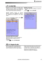
Page 29: ...t the NAVTEX icon Reloading NAVTEX messages NAVTEX messages need to be loaded from NAVTEX receiver manually Up to 50 messages 1 Press and select Reload all Deleting a message 1 Move the cursor to a me...

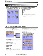
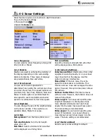
Page 30: ...System configuration 1 Press and hold 2 Select the system configuration icon 4 1 1 Language Change the language for menus and data screens 4 1 2 Beep volume Select the level of beep sound 4 1 3 Auto...

Page 31: ...or off Fish depth labels Turn the fish depth value on or off Fish filter Select a minimum fish size that will be displayed as a fish symbol Fish sensitivity Select the minimum strength fish echo that...

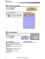
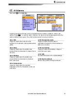
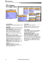
Page 32: ...mages on the user card 4 4 AIS Settings Note AIS feature require an optional AIS receiver To go to the AIS settings 1 Press and hold 2 Select the AIS icon 4 4 1 Alarm option Dangerous Vessel Alarm Whe...

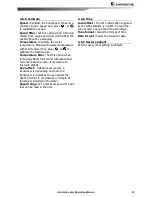
Page 33: ...Trigger an alarm when the depth value received from the transducer is deeper than a set value 4 5 3 Shallow Trigger an alarm when the depth value received from the transducer is shallower than a set v...

Page 34: ...the value of stable speed and course information Lat Lon d p s Select number of last digit of Lat Lon to be sent to other marine electronics Magnetic Variation This option compensates the difference...

Page 35: ...n removing effects form water turbulence and currents cause the water temperature to fluctuate slightly Keel offset A depth measured by a transducer is depending on where the transducer is installed Y...

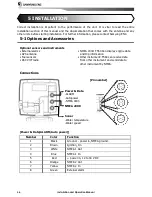
Page 36: ...nts External alarms GPS antenna Fuel sensors DSC VHF radio NMEA 2000 F560 Can display engine data and trip information Other instrument F560 can receive data from other instrument and send data to oth...

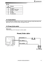
Page 37: ...GND 5 2 Connections The fish finder has connectors that are used to connect to the power supply GPS antenna and NMEA device such as VHF AIS receiver and digital instruments 5 3 Power data cable Basic...

Page 38: ...Wire the fish finder for any external alarm beepers or lights as below picture The output from the unit to external alarm is maximum 30V DC 200mA It is needed to fit a suitable relay Power Data cable...

Page 39: ...al NMEA instruments as above pictures The fish finder can receive and display depth paddlewheel boat speed and water temperature from an optional compatible instrument The fish finder can receive data...

Page 40: ...llowings Engines have fuel flow sensors therefore fuel sensors are not required F560 can receive and display wind speed and direction from an optional compatible wind instrument N560 can receive and d...

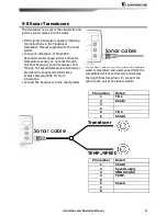
Page 41: ...ll dual frequency sonar transducer and through hull speed temperature transducer provide more enhanced performance Contact Samyung ENC for more information Connect the transducer to the chart plotter...

Page 42: ...2 If the display unit is bracket mounted adjust tilt and rotation for best viewing and hand tighten the knob 3 Install an optional instrument and connect F560 to the optional instrument to make sure...

Page 43: ...l costs associated with transducer replacement other than the cost of the transducer itself 3 Routine system checkouts alignment and calibration seatrials unless required by replacement of defective p...

Page 44: ...Installation and Operation Manual 44...

Reviews: