SAMWON ENG SU-105 Instrument for Automatic Control of Temperature Page
2/4
A B B
+ -
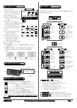
① How to wire sensor.
▶ Connect the wire as shown in the
picture in right. Wrong wiring shall
cause an error.
”
Err
”
in display.
②How to extend sensor wire.
▶In case to extend RTDsensor and
K, T sensor, refer to caution 11 and
12 in Page 1.
▶Extension of IC, humidity and
themistor sensor is available within 100m.
▶ Use the wire which has a shield
In order to prevent any noise
input, when you want to extend cable
of sensor.
③ How to compensate the variation.
(when current indicator of
temperature is wrong.)
▶ A long sensor wire and a old
sensor may cause a variation in
temperature. Compensation
feature(rSt) could be used.
▶ At current temperature, press set
key for 3~ seconds.
▶ Release setkey when dIF or P is displayed. Setkey several times to
move to rSt.
▶ Up(up),Down(dn)key to input the compensation. Set key for 3~
seconds will memorize and amended value will be displayed.
Such as
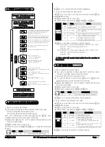
① By using lock feature, installer
’
s reset could be prevented.
PRE
SET
at
FAC.
Item
Value
EXPLANATION
LoC
OFF
Release of lock and reset of all feature are
available.
ON
Locked. All of reset is not available, except
preset of temperature.
Item
Value
EXPLANATION
StH
50
Up limit of temperature to 50 degree.
StL
40
Down limit of temperature to 40 degree.
▶ set key for3~ seconds will memorize the value as effective from that
time on. ※ Since then, reset if temperature is available in the range of
50℃~40℃only.
▶ Main output could be reset by using the bellows. (set key will skip to
next step at every pressing.)
* Example : DIF and TYP input value
① TYP = at C(cooler(in reverse direction)) state
ex) assuming of preset temperature 10.0℃, DIF = 2.0,
Relay ON : 12.1℃, Relay OFF : 10.0℃
② TYP = at H(heater(in right direction)) state
ex) assuming of preset temperature 10.0℃, DIF = 2.0,
Relay ON : 7.9℃, Relay OFF : 10℃
* assuming dLt=10, Relay will be ON in 10 seconds.
* assuming tyP = C(cooler), will be used for lowing temperature.
* assuming tyP = H(heater), will be used for increasing temp.
Sensor
input
Main
output
Aux
output
Power
RELAY
5A
RELAY
2A
AC
100~
240V
① ② ③ ④ ⑤ ⑥ ⑦ ⑧ ⑨ ⑩ ⑪
⑫
Sensor
①
②
③
K
red/whit
e
Black
PT100
White
Black
Black
Black
IC
Black
White
Red
Current
temperature
compensation
temperature
(r
St)
Displayed
current
temperature
20 ℃
+
+
-5 ℃
=
=
15 ℃
20 ℃
10 ℃
30 ℃
4. How to wire Sensor
5. Out appearance for panel
< Terminal at
back>
70
34
76
(unit: mm)
28+
0.6
PANEL CUT OUT
70
+0.6
7 Installer
’
s RESET
Ins
ta
lle
r
’
s
R
E
S
E
T
(O
U
T1
)
On/Off control ▲▼
Output Range
(On~OFF)
0.1~25.0℃
ON Delay timer
0sec~300sec
△▽ selectable
C:Cooler
H:Heater
Set Key for 3~ seconds at
current state.
PI control
6. Limit of RESET, Lock of RESET
proportional(0.1~50.0):
small proportional result
a fast target value, but
bigger overshoot.
Integral compensation :
to remove the error to
target value. Small value
will act fast, but may
cause haunting
Period time
(1~120sec.) : will decide
the period of ON/OFF in
Relay Output.
Compensation
of sensor -
30~+30
Alarm Output
Aux output reset
temperature :
Separate Targert
value from OUT1 is
available
Range between
Output for SV2 OFF
and Output ON SV2
(0.1~25.0)
Aux output delay
timer (0~300sec.)
Timer Output
Select operating time .
0~999 minutes
0~999 seconds
Reset timer.
ON: ON operating first
OFF: OFF operating first
ON time:0~999(min/sec)
*caution : acknowledged as
0: waiting for ON
∞ : OFFstate
Ins
ta
lle
r
’
s
S
E
T
(O
U
T2
)
△▽ selectable aux.
output,
C:cooler,H:heater
OFF time :0~999(min/sec)
*caution :acknowledged as
0 : witing fir OFF
∞ : ON state
Set key to go back start-up
.
누르면 처음으로 돌아갑니다
.
Set key for 3~ seconds will memorize
the value, will go back to current state.


