94
Click
to restore the default values immediately.
Connect Monitor Board
Monitor Boards are required for certain status and parameters monitoring. Select this
option to get those status and parameters under monitoring.
Refresh Humidity
If this option is selected, the humidity within the cabinets will be under monitoring.
Refresh Smoke
If this option is selected, the smoke within the cabinets will be under monitoring.
Refresh cabinet status
If this option is selected, the working status of the cabinets will be under monitoring.
Refresh status of Cabinet-Door
If this option is selected, the open/close status of the cabinet doors will be under
monitoring.
Refresh Fan
If this option is selected, the fans status will be under monitoring.
Every cabinet has the same number of fan
If for every cabinet, the number of fans to be monitored is the same, select this option and
set the fan number in the box to the right of this option.
Ever cabinet has the different number of fan
If the numbers of fans to be monitored are different from one cabinet to another, select this
option and click the
Setting
button to set the fan numbers for each cabinet.
Refresh the power supply of the monitoring card
If this option is selected, the power supplies on the monitor board will be under monitoring.
Every monitoring card has the same number of power supply
If for every monitor board, the number of power supplies to be monitored is the same,
select this option and set the power supplies number in the box to the right of this option.
Number of power supply separately set on monitoring card
If the numbers of power supplies to be monitored are different from one monitor board to
another, select this option and click the
Setting
button to set the power supplies numbers
for each cabinet.
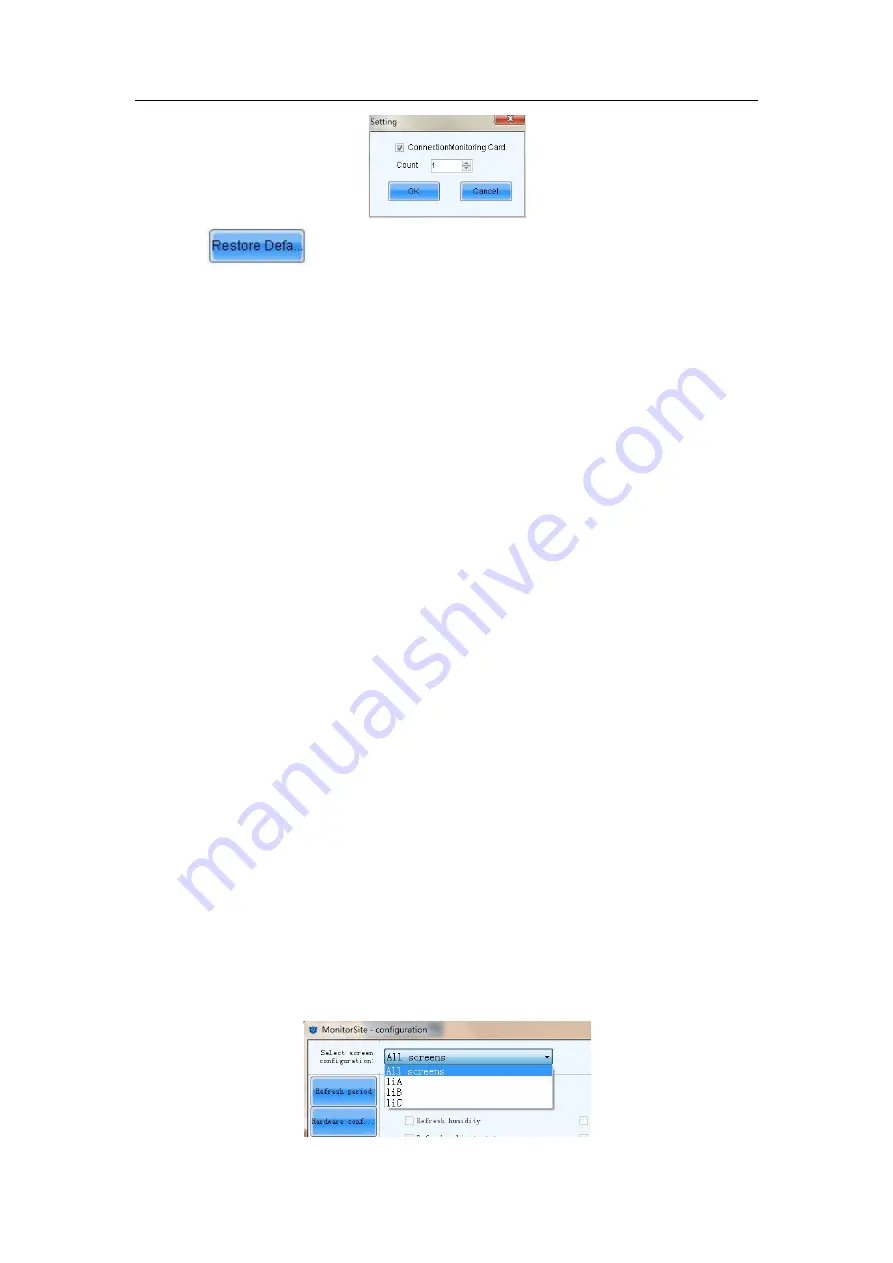
Select screen configuration:
Select “All screens” to perform refreshing setting uniformly, or perform refreshing setting
to every screen separately.
Summary of Contents for XA100F
Page 1: ...1 Outdoor P10 Product User Manual Model Name XA100F Model Code LH100XAFSSC ...
Page 11: ...11 3 2 Product Appearance ...
Page 12: ...12 3 3 Product design Decomposition chart ...
Page 13: ...13 Assembly drawing ...
Page 14: ...14 3 4 Product main components Module Power Supply Receiving card Fan ...
Page 15: ...15 DC output cables 9 pcs Flat cables 9 pcs ...
Page 33: ...33 Installation of cabinets Fixing of connect plate ...
Page 39: ...39 8 2 Port of Cabinet and serial number paint ...
Page 56: ...56 ...
Page 65: ...65 ...
Page 98: ...98 ...
Page 114: ...114 Install the cover for connection cable Power on the cabinet ...
Page 115: ...115 Signal input cable and Signal cascade cable Remove the bad one Install the new one ...


