


3. Alignment and Adjustments
3-19
1) Screen Scroll
Eliminates the afterimages that can result when the still
image is displayed for prolonged periods. Use Interval to
set the repeat cycle by time unit and use Second to set the
repeat cycle by second unit. Select one of 4 types- Scroll,
Pixel, Bar, Eraser.
- The Maintenance Control feature is available only for the
displays whose power status in ON.
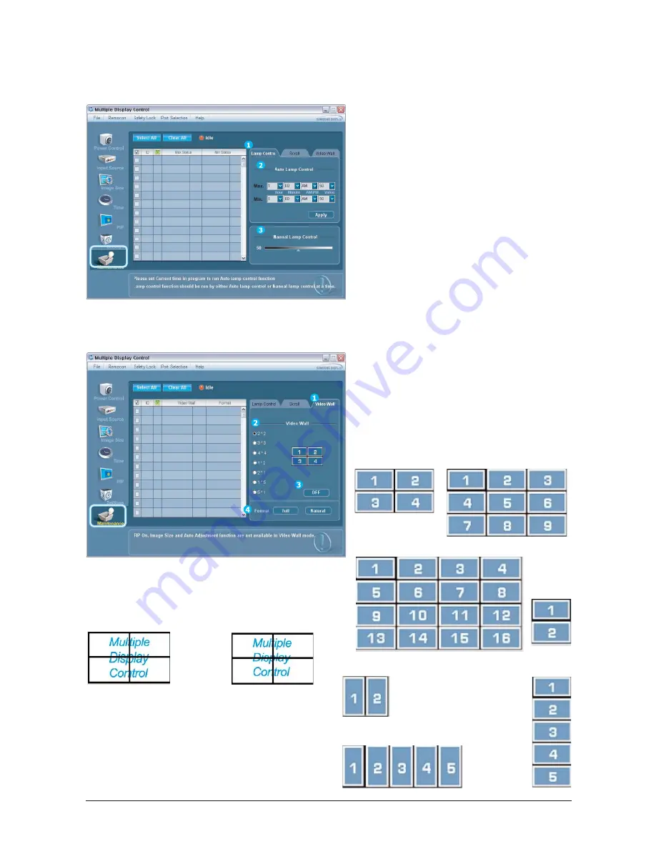
-Maintenance Control - Lamp Control
1. Click Maintenance of the main icons and select the Scroll tab to display the Maintenance Control.
1) Video Wall
A Video Wall is a set of video screens that are connected
together, so that each screen shows a part of the whole
picture or so that the same picture is repeated on each
screen.
2) Video Wall (Screen Divider)
You can select a number of screens with a different layout
when dividing.
3) On / Off
Turns On or Off the Video Wall function of the selected
display.
4) Format
The format can be selected to see a divided screen.
This feature is available only for the displays whose power
status in IN and if no selection is made, the factory default is
displayed.
The Malignant Input operates only in MagicNet models.
Full
Natural
-Maintenance Control - Video Wall
1. Click Maintenance of the main icons and select the Wall tab to display the Maintenance Control window.
2 * 2
3 * 3
4 * 4
1 * 2
1 * 5
5 * 1
2 * 1
Summary of Contents for SyncMaster 400TXn
Page 9: ...Memo 1 Precautions 1 4...
Page 25: ...3 Alignment and Adjustments 3 10 5 Yes Click 6 OK Click...
Page 41: ...3 Alignment and Adjustments 3 26 Memo...
Page 43: ...4 Troubleshooting 4 2 WAVEFORMS 1 2 4 3 CN602 C653 C622 C603...
Page 45: ...4 Troubleshooting 4 4 5 5 5 5 WAVEFORMS IC101 is on the rear board of IC103...
Page 47: ...4 Troubleshooting 4 6 7 8 WAVEFORMS IC101 is on the rear board of IC103...
Page 49: ...4 Troubleshooting 4 8 5 6 WAVEFORMS 9 10...
Page 70: ...14 1 1 7 7 46 46 46 0 10 5 3 7 46 7 7 7...
Page 71: ...14 2 7 3 7 7 3 7 7 7 0 7 4 7 0 4 7 4 4 7 4 7 3 3 7 6 0 3 4063 4...
Page 72: ...14 3 7 0 10 5 6 0 6 0 3 7 0 10 5 13 1 4063 7...
Page 73: ...14 4 7 7 6 0 3 7 7 0 4063...
Page 74: ...14 5 7 0 10 5 6 0 6 0 3 0 10 5 13 1 13 1 4063...
Page 75: ...14 6 69 3 0 503 065 6 0 3...
Page 77: ...14 8 7 45 1C 1S 7 45...
Page 80: ...14 11 57 5 57 4 4 4 57...
Page 92: ...8 1 8 Wiring Diagram 8 Wiring Diagram 8 1 Main Board Wiring Diagram...
Page 93: ...8 Wiring Diagram 8 2 8 2 Network Board Wiring Diagram...
Page 98: ...9 5 9 4DIFNBUJD JBHSBN 9 5 IP board Schematics Diagram 1...
Page 99: ...9 4DIFNBUJD JBHSBN 9 6 9 6 IP board Schematics Diagram 2...
Page 100: ...9 7 9 4DIFNBUJD JBHSBN 9 7 IP board Schematics Diagram 2...
Page 101: ...9 4DIFNBUJD JBHSBN 9 8 9 8 Sub power Schematics Diagram...
Page 103: ...9 Schematic Diagram 9 10...
Page 112: ...9 Schematic Diagram 9 19...
Page 113: ...9 Schematic Diagram 9 20...
Page 114: ...9 Schematic Diagram 9 21...
Page 115: ...9 Schematic Diagram 9 22...
Page 116: ...9 Schematic Diagram 9 23...
Page 117: ...9 Schematic Diagram 9 24...
Page 118: ...9 Schematic Diagram 9 25...
Page 119: ...9 Schematic Diagram 9 26...
Page 120: ...9 Schematic Diagram 9 27...
Page 121: ...9 Schematic Diagram 9 28...
Page 122: ...9 Schematic Diagram 9 29...
Page 123: ...9 Schematic Diagram 9 30...
Page 124: ...9 Schematic Diagram 9 31...
Page 125: ...9 Schematic Diagram 9 32...
Page 126: ...9 Schematic Diagram 9 33...
Page 127: ...Memo 9 Schematic Diagram 9 34...
Page 143: ...12 PCB layout 12 2 12 2 Network PCB layout LAN USB...
Page 144: ...12 PCB layout 12 3 12 3 IP board layout...
Page 145: ...12 PCB layout 12 4 12 4 Network Power board layout...
Page 151: ...JSDVJU FTDSJQUJPOT 13 6 Memo...
Page 171: ...14 Reference Infomation 14 20 Memo...


