


3. Alignment and Adjustments
3-17
- Info Grid shows some basic information necessary to
Setting Control. When each function is selected, the set
value of the selected function is displayed in the slide. As
you select Select All, the value is returned to the default
setting (50).
Changing a value in this screen will automatically change
the mode to "CUSTOM."
1) Picture PC
Available only for PC, BNC, and DVI.
2) Contrast
Adjusts Contrast of the selected display.
3) Brightness
Adjusts Brightness of the selected display.
4) Red
Adjusts Red Color of the selected display.
5) Green
Adjusts Green Color of the selected display.
6) Blue
Adjusts Blue Color of he selected display.
This feature is available only for the displays whose power status is
ON and if no selection is made, the factory default is displayed.
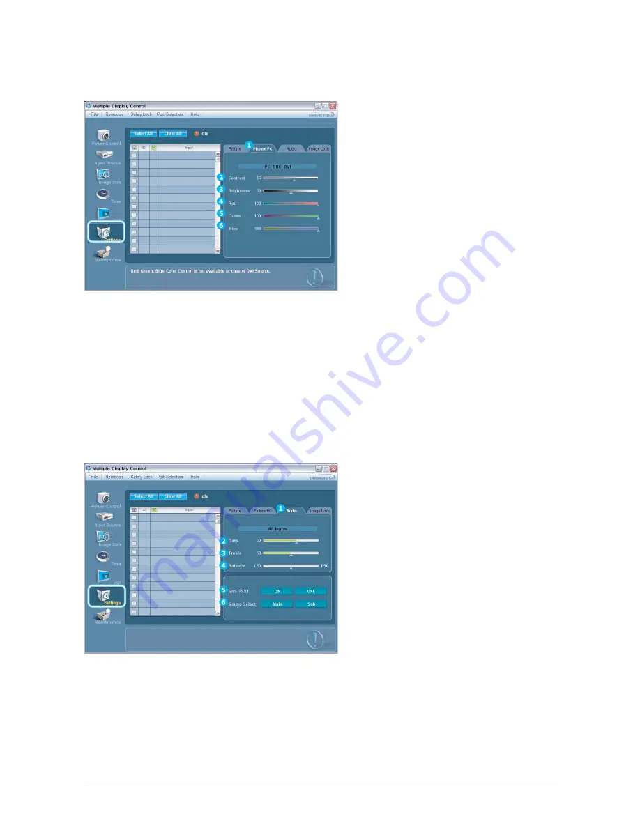
-Setting Control - Picture PC
1. Click Setting of the main icons and select the Picture PC tab to display the Setting Control window.
- Info Grid shows some basic information necessary to
Setting Control. When each function is selected, the set
value of the selected function is displayed in the slide. As
you select Select All, the value is returned to the default
setting (50).
Changing a value in this screen will automatically change
the mode to "CUSTOM."
1) Audio
Controls audio setting for all input sources.
2) Bass
Adjusts Bass of the selected display.
3) Treble
Adjusts Treble of the selected display.
4) Balance
Adjusts Balance of the selected display.
5) SRS TSXT
Turns the SRS Trusurround XT function of the selected
display On/Off.
6) Sound Select
Select either Main or Sub when the PIP of the selected
display is turned On.
This feature is available only for the displays whose power status in
IN and if no selection is made, the factory default is displayed.
The MagicNet Input operates only in MagicNet models.
-Setting Control - Audio
1. Click Settings of the main icons and select the Audio tab to display the Setting Control window.
Summary of Contents for SyncMaster 400TXn
Page 9: ...Memo 1 Precautions 1 4...
Page 25: ...3 Alignment and Adjustments 3 10 5 Yes Click 6 OK Click...
Page 41: ...3 Alignment and Adjustments 3 26 Memo...
Page 43: ...4 Troubleshooting 4 2 WAVEFORMS 1 2 4 3 CN602 C653 C622 C603...
Page 45: ...4 Troubleshooting 4 4 5 5 5 5 WAVEFORMS IC101 is on the rear board of IC103...
Page 47: ...4 Troubleshooting 4 6 7 8 WAVEFORMS IC101 is on the rear board of IC103...
Page 49: ...4 Troubleshooting 4 8 5 6 WAVEFORMS 9 10...
Page 70: ...14 1 1 7 7 46 46 46 0 10 5 3 7 46 7 7 7...
Page 71: ...14 2 7 3 7 7 3 7 7 7 0 7 4 7 0 4 7 4 4 7 4 7 3 3 7 6 0 3 4063 4...
Page 72: ...14 3 7 0 10 5 6 0 6 0 3 7 0 10 5 13 1 4063 7...
Page 73: ...14 4 7 7 6 0 3 7 7 0 4063...
Page 74: ...14 5 7 0 10 5 6 0 6 0 3 0 10 5 13 1 13 1 4063...
Page 75: ...14 6 69 3 0 503 065 6 0 3...
Page 77: ...14 8 7 45 1C 1S 7 45...
Page 80: ...14 11 57 5 57 4 4 4 57...
Page 92: ...8 1 8 Wiring Diagram 8 Wiring Diagram 8 1 Main Board Wiring Diagram...
Page 93: ...8 Wiring Diagram 8 2 8 2 Network Board Wiring Diagram...
Page 98: ...9 5 9 4DIFNBUJD JBHSBN 9 5 IP board Schematics Diagram 1...
Page 99: ...9 4DIFNBUJD JBHSBN 9 6 9 6 IP board Schematics Diagram 2...
Page 100: ...9 7 9 4DIFNBUJD JBHSBN 9 7 IP board Schematics Diagram 2...
Page 101: ...9 4DIFNBUJD JBHSBN 9 8 9 8 Sub power Schematics Diagram...
Page 103: ...9 Schematic Diagram 9 10...
Page 112: ...9 Schematic Diagram 9 19...
Page 113: ...9 Schematic Diagram 9 20...
Page 114: ...9 Schematic Diagram 9 21...
Page 115: ...9 Schematic Diagram 9 22...
Page 116: ...9 Schematic Diagram 9 23...
Page 117: ...9 Schematic Diagram 9 24...
Page 118: ...9 Schematic Diagram 9 25...
Page 119: ...9 Schematic Diagram 9 26...
Page 120: ...9 Schematic Diagram 9 27...
Page 121: ...9 Schematic Diagram 9 28...
Page 122: ...9 Schematic Diagram 9 29...
Page 123: ...9 Schematic Diagram 9 30...
Page 124: ...9 Schematic Diagram 9 31...
Page 125: ...9 Schematic Diagram 9 32...
Page 126: ...9 Schematic Diagram 9 33...
Page 127: ...Memo 9 Schematic Diagram 9 34...
Page 143: ...12 PCB layout 12 2 12 2 Network PCB layout LAN USB...
Page 144: ...12 PCB layout 12 3 12 3 IP board layout...
Page 145: ...12 PCB layout 12 4 12 4 Network Power board layout...
Page 151: ...JSDVJU FTDSJQUJPOT 13 6 Memo...
Page 171: ...14 Reference Infomation 14 20 Memo...


