


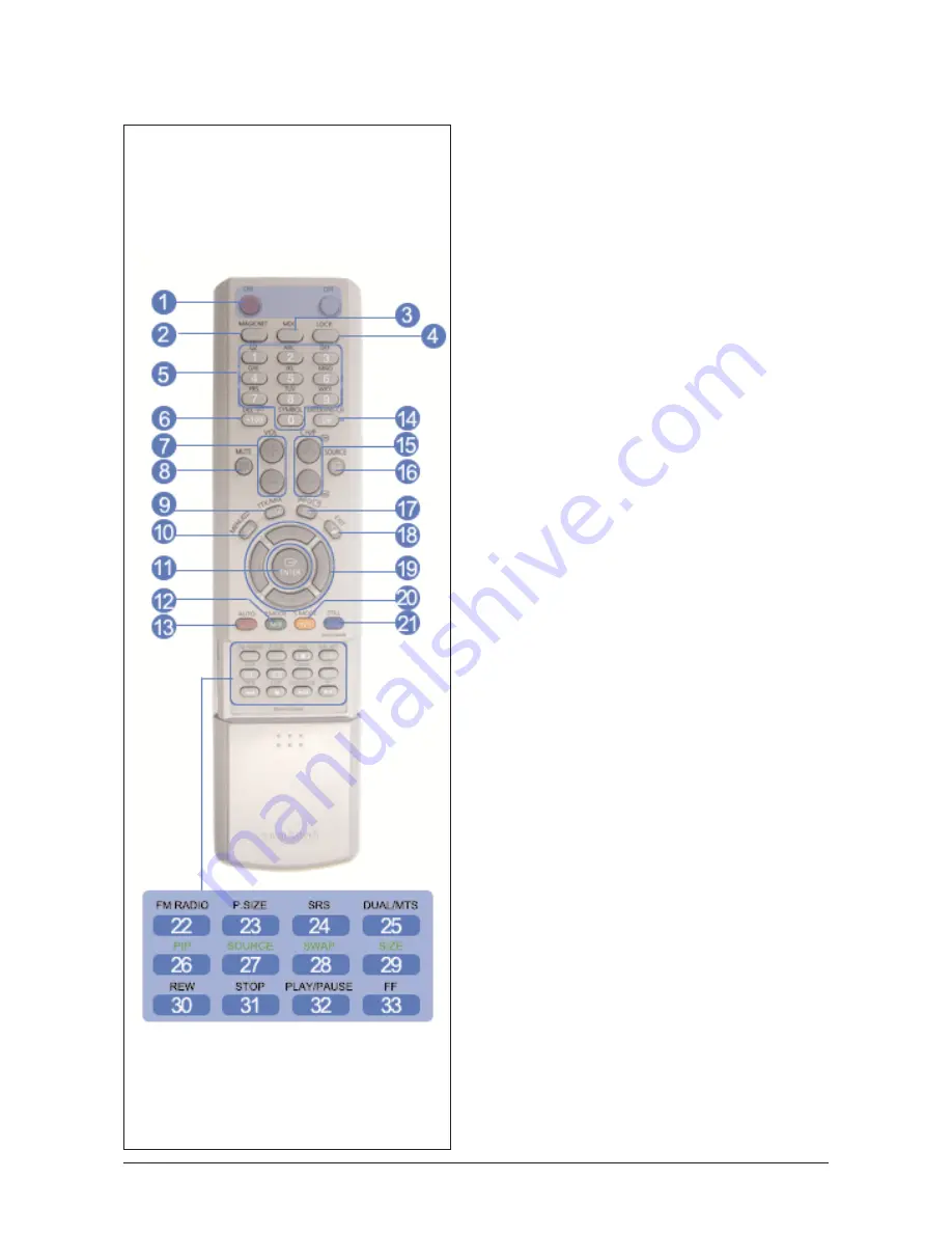
10-1-2 Remote Control
1) ON / OFF
Use these buttons to turn the monitor on or off.
2) MAGICNET
MagicNet Quick Launch Button.
3) MDC
MDC Quick Launch Button.
4) LOCK
This button will activate or deactivate all function
keys on both the remote control and the monitor
except for the Power and LOCK buttons.
5) MagicNet buttons
Used for MagicNet. ? Alphanumeric: Used to enter
the Internet address.
- DEL: Functions as the backspace.
- SYMBOL: Used to enter the symbols. (.O_-:/)
- ENTER: Used to enter values.
6) +100
Press to select channels over 100.
For example, to select channel 121, press "+100",
then press "2" and "1".
[This fuction does not work for this monitor.]
7) VOL
Adjusts the audio volume.
8) MUTE
Pauses (mutes) the audio output temporarily.
Displayed on the lower left corner of the screen.
The audio resumes if MUTE or - VOL + is pressed
in the Mute mode.
9) TTX/MIX
TV channels provide written information services via
teletext.
[This function is available only in Europe. ]
10) MENU
Use this button to open the on-screen menu and
exit from the menu screen or close screen adjust
ment menu.
11) ENTER
Activate a highlighted menu item.
12) P.MODE
This button is used to return to the immediately pre
vious channel.
[This fuction does not work for this monitor.]
13) AUTO
Adjusts the screen display automatically.
If you change resolution in the control panel, auto
function will be executed.
10 Operating Instructions and Installation
10-7
Summary of Contents for SyncMaster 400TXn
Page 9: ...Memo 1 Precautions 1 4...
Page 25: ...3 Alignment and Adjustments 3 10 5 Yes Click 6 OK Click...
Page 41: ...3 Alignment and Adjustments 3 26 Memo...
Page 43: ...4 Troubleshooting 4 2 WAVEFORMS 1 2 4 3 CN602 C653 C622 C603...
Page 45: ...4 Troubleshooting 4 4 5 5 5 5 WAVEFORMS IC101 is on the rear board of IC103...
Page 47: ...4 Troubleshooting 4 6 7 8 WAVEFORMS IC101 is on the rear board of IC103...
Page 49: ...4 Troubleshooting 4 8 5 6 WAVEFORMS 9 10...
Page 70: ...14 1 1 7 7 46 46 46 0 10 5 3 7 46 7 7 7...
Page 71: ...14 2 7 3 7 7 3 7 7 7 0 7 4 7 0 4 7 4 4 7 4 7 3 3 7 6 0 3 4063 4...
Page 72: ...14 3 7 0 10 5 6 0 6 0 3 7 0 10 5 13 1 4063 7...
Page 73: ...14 4 7 7 6 0 3 7 7 0 4063...
Page 74: ...14 5 7 0 10 5 6 0 6 0 3 0 10 5 13 1 13 1 4063...
Page 75: ...14 6 69 3 0 503 065 6 0 3...
Page 77: ...14 8 7 45 1C 1S 7 45...
Page 80: ...14 11 57 5 57 4 4 4 57...
Page 92: ...8 1 8 Wiring Diagram 8 Wiring Diagram 8 1 Main Board Wiring Diagram...
Page 93: ...8 Wiring Diagram 8 2 8 2 Network Board Wiring Diagram...
Page 98: ...9 5 9 4DIFNBUJD JBHSBN 9 5 IP board Schematics Diagram 1...
Page 99: ...9 4DIFNBUJD JBHSBN 9 6 9 6 IP board Schematics Diagram 2...
Page 100: ...9 7 9 4DIFNBUJD JBHSBN 9 7 IP board Schematics Diagram 2...
Page 101: ...9 4DIFNBUJD JBHSBN 9 8 9 8 Sub power Schematics Diagram...
Page 103: ...9 Schematic Diagram 9 10...
Page 112: ...9 Schematic Diagram 9 19...
Page 113: ...9 Schematic Diagram 9 20...
Page 114: ...9 Schematic Diagram 9 21...
Page 115: ...9 Schematic Diagram 9 22...
Page 116: ...9 Schematic Diagram 9 23...
Page 117: ...9 Schematic Diagram 9 24...
Page 118: ...9 Schematic Diagram 9 25...
Page 119: ...9 Schematic Diagram 9 26...
Page 120: ...9 Schematic Diagram 9 27...
Page 121: ...9 Schematic Diagram 9 28...
Page 122: ...9 Schematic Diagram 9 29...
Page 123: ...9 Schematic Diagram 9 30...
Page 124: ...9 Schematic Diagram 9 31...
Page 125: ...9 Schematic Diagram 9 32...
Page 126: ...9 Schematic Diagram 9 33...
Page 127: ...Memo 9 Schematic Diagram 9 34...
Page 143: ...12 PCB layout 12 2 12 2 Network PCB layout LAN USB...
Page 144: ...12 PCB layout 12 3 12 3 IP board layout...
Page 145: ...12 PCB layout 12 4 12 4 Network Power board layout...
Page 151: ...JSDVJU FTDSJQUJPOT 13 6 Memo...
Page 171: ...14 Reference Infomation 14 20 Memo...


