


Operating Instructions
Samsung Electronics
4-5
15
14
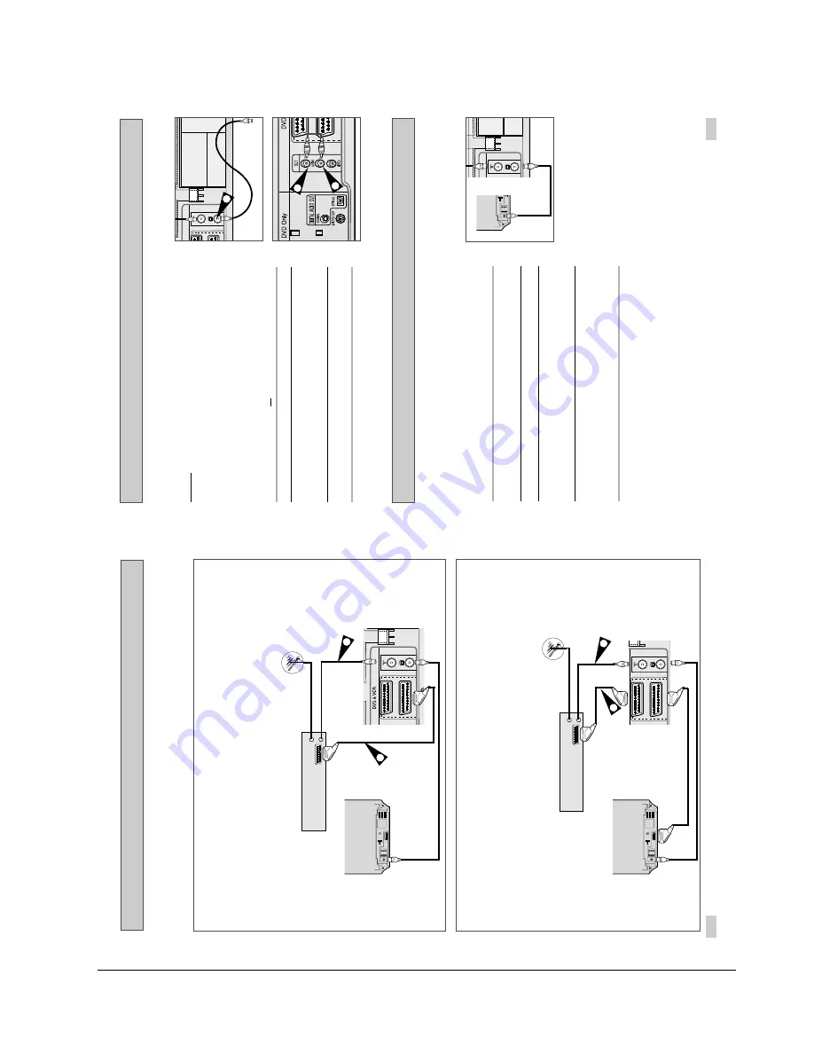
Connecting the Audio Output Cable
Plug & Auto Set Up
Your DVD-VCR will automatically set itself up when it is plugged
into the mains for the first time. TV stations will be stored in
memory. The process takes a few minutes. Your DVD-VCR will
then be ready for use.
1
Connect the coaxial cable as indicated on page 13.
(Connecting Your DVD-VCR to the TV Using the Coaxial Cable)
2
Plug the DVD-VCR into the mains.
3
Start the auto scanning.
◆
The number of stations automatically stored by the DVD-VCR
depends on the number of stations that it has found.
4
The current time and date are displayed automatically.
Check the date and time.
if it is :
◆
Incorrect, see page 19.
➢
Now, you only have to switch the DVD-VCR on and it is
ready for use.
☛
Function for “Plug & Auto Set Up” is fixed already.
So if you want to change this fixed one, you can change
it by Presetting the Stations Automatically in OSD “ Auto
Setup” menu. (see page 21)
You can connect your DVD-VCR to a Hi-Fi system.
Example
:
You wish to take advantage of the quality of your Hi-Fi
stereo system when watching a programme or recording
via your DVD-VCR.
☛
◆
Regardless of the type of connection chosen, you
must always connect the coaxial cable supplied.
Otherwise, no picture will be visible on the screen
when the DVD-VCR is switched off.
◆
Make sure that both the television and the DVD-VCR
are switched off
before connecting the cables.
1
Connect the coaxial cable or SCART as indicated on page 13.
2
Plug the audio output cable into the audio connectors on the rear
of your DVD-VCR.
➢
Respect the colour coding of the left and right channels.
3
Plug the other end of the audio cable into the appropriate input
connectors on your Hi-Fi stereo system.
AV2 (D
AV1 (
2
2
TV
1
TV
AV2 (DEC./EXT)
AV1 (EURO AV)
TV
Connecting DVD-VCR to a Satellite Receiver or Other Equipment
1. AV2 IN: By means of 21-pin Scart Cable
Plug the SCART Cable with satellite receiver or other equipment into the AV2 (DEC./EXT.) socket on the rear of
the DVD-VCR.
After making this connection, select the source by pressing the INPUT SEL. button for the AV2 input sources.
2. By means of RF Coaxial Cable
After making this connection, you must preset the station received through the satellite tuner.
RF output channel of the satellite receiver should be adjusted away from channel 60, which is used by the
DVD-VCR, e.g. re-adjust to channel 65.
Satellite Receiver or other Equipment
1. AV1(EURO AV): By means of 21-pin Scart Cable
Plug the SCART Cable with satellite receiver or other equipment into the AV1 (EURO AV) socket on the rear of the
DVD-VCR.
After making this connection, select the source by pressing the INPUT SEL. button for the AV1 input sources.
2. By means of RF Coaxial Cable
After making this connection, you must preset the station received through the satellite tuner.
RF output channel of the satellite receiver should be adjusted away from channel 60, which is used by the
DVD-VCR, e.g. re-adjust to channel 65.
Aerial
Aerial Connector
TV
AV2 (DEC./EXT)
AV1 (EURO AV)
SCART Cable
RF coaxial cable
1
2
TV
Satellite Receiver or other Equipment
Aerial
Aerial Connector
TV
AV2 (DEC./EXT)
AV1 (EURO AV)
SCART Cable
RF coaxial cable
1
2
TV
You can connect your DVD-VCR to a Satellite receiver or other DVD-VCR using the SCART cable if the
appropriate outputs are available on the equipment chosen. The following illustrations give a few examples
of the connection possibilities.
Summary of Contents for SV-DVD50
Page 26: ...Exploded View and Parts List 3 10 Samsung Electronics MEMO ...
Page 88: ...VCR Deck Operating Description 8 12 Samsung Electronics Fig 8 14 Mecha Timing Chart ...
Page 102: ...VCR Deck Operating Description 8 26 Samsung Electronics MEMO ...
Page 109: ...Circuit Operating Descriptions 7 7 Fig 7 12 Block Diagram ...
Page 143: ...Circuit Operating Descriptions 7 41 3 Block Diagram Fig 7 38 LA70100M Block Diagram ...
Page 158: ...Block Diagram 10 2 Samsung Electronics MEMO ...
Page 159: ...Samsung Electronics 11 1 11 Wiring Diagram ...
Page 160: ...Block Diagram 11 2 Samsung Electronics MEMO ...
Page 162: ...Schematic Diagrams 12 2 Samsung Electronics 6 1 S M P S ...
Page 163: ...Schematic Diagrams Samsung Electronics 12 3 6 2 Power Drive ...
Page 164: ...Schematic Diagrams 12 4 Samsung Electronics DT701 6 3 Display Function ...
Page 165: ...Schematic Diagrams Samsung Electronics 12 5 6 4 System Control Servo ...
Page 166: ...Schematic Diagrams 12 6 Samsung Electronics 6 5 A V ...
Page 167: ...Schematic Diagrams Samsung Electronics 12 7 6 6 Hi Fi ...
Page 168: ...Schematic Diagrams 12 8 Samsung Electronics 6 7 A2 NICAM ...
Page 169: ...Schematic Diagrams Samsung Electronics 12 9 6 8 SECAM Option ...
Page 170: ...Schematic Diagrams 12 10 Samsung Electronics 6 9 OSD VPS PDC ...
Page 171: ...Schematic Diagrams Samsung Electronics 12 11 6 10 TM ...
Page 172: ...Schematic Diagrams 12 12 Samsung Electronics 6 11 Input Output ...
Page 173: ...Schematic Diagrams Samsung Electronics 12 13 6 12 DVD AV Decoder ...
Page 174: ...Schematic Diagrams 12 14 Samsung Electronics 6 13 DVD Servo ...
Page 175: ...Schematic Diagrams Samsung Electronics 12 15 6 14 DVD Audio Video ...
Page 176: ...Schematic Diagrams 12 16 Samsung Electronics MEMO ...


