background image

7-2

GB

7-1

1

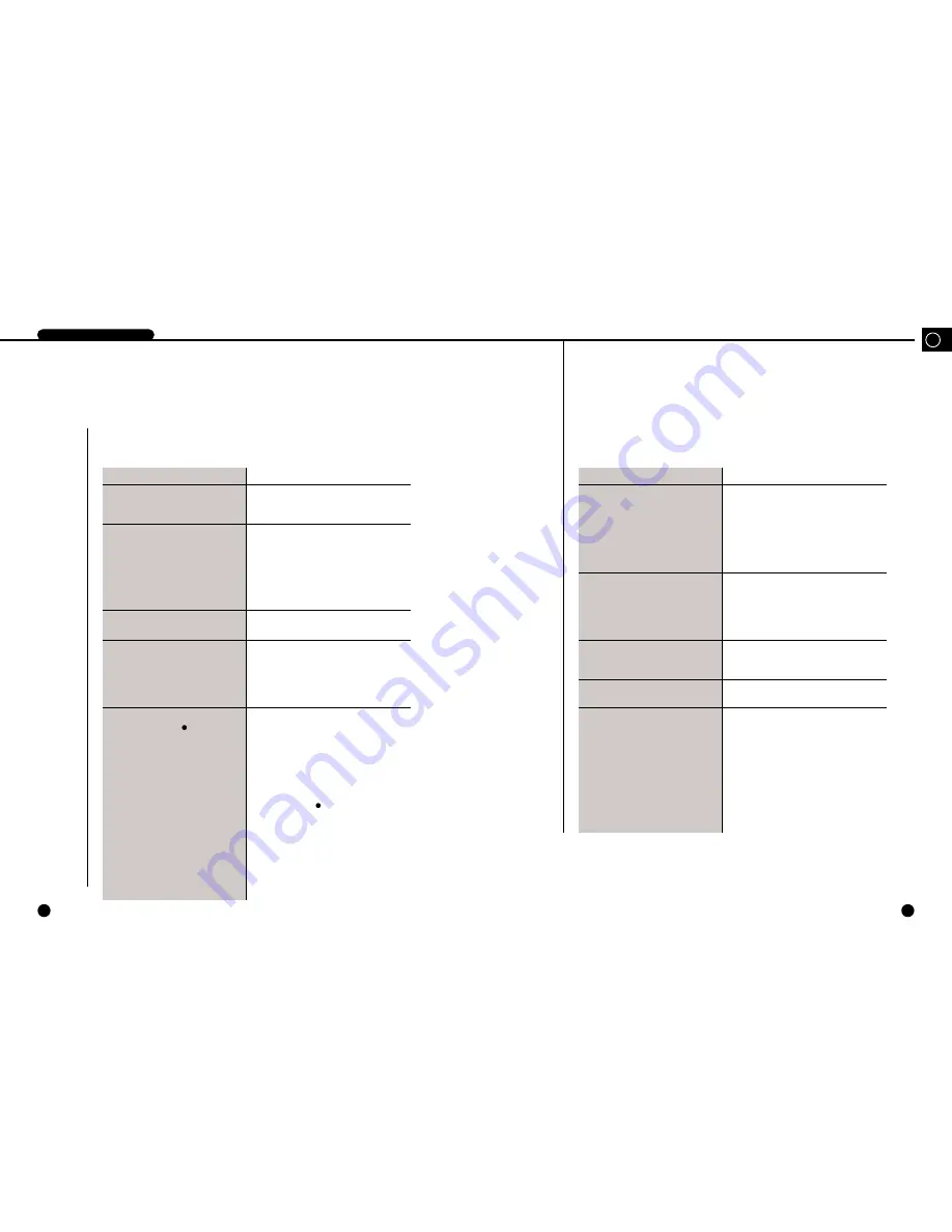
Check Points before Call Service Center

DIGITAL VIDEO RECORDER

If the system malfunctions, please check the following instruction before you call the service

center or the shop where you bought the system.

Trouble

Check Points

• Unable to supply power.

• The POWER LED in front of the system

remains off and the system is not running

• After power supply, the screen is all black.

• After booting, the screen is all blue

• After power supply, no further progress

available after booting menu screen

• No voice

• Unable to record.

• The RECORD button (     ) can't activate

recording.

– Check the power cable connection behind the

system, power supply, and power switch.

– Check the power cable connection of the system and

monitor and power supply.

– Check the connection between camera output port

and system image signal input port and between

monitor image signal input port and system image

signal output port.

– Check the camera output.

– Check the BNC Cable connected to the system.

– Please call the service center or the shop where you

bought the product for investigation or repair.

– Check the connection between microphone voice

output port and system voice signal input port and

between monitor voice signal input port and system

voice signal output port.

– Check the voice signal output.

– Check the connected cable.

– Without input signal, the system can't perform

recording. Please check if the camera output port is

well connected.

– As long as the free HDD space ratio remains 0%

and the FULL indicating LED in front the of system

remains on, the system will not start recording.

– To start recording as it is like above, you should set

the DISK END MODE in the RECORD MODE

SETUP menu to CONTINUE and press the

RECORD / button(     ).

– To start recording while the DISK END MODE is

set to STOP, you should set the CLEAR ALL DATA

in SYSTEM SETUP menu to ON and terminate the

menu. Then, all the current data will be deleted. Now,

you should press the RECORD button() to start

recording.

However, as the deleted data can not be recovered by

all means, you should check again before deleting.

Trouble

Check Points

• Abnormal recording and playing after

connected to the Multiplexer

• No voice during play

• The screen trembles vertically during play.

• Interval between image and voice during

play

• Garbled screen during play

– Check the connection between Multiplexer image

output port and system image signal input port and

between Multiplexer image signal input port and

system image signal output port.

– Check the connection between system trigger output

port(Trigger Out) and Multiplexer.

– For the details of the Multiplexer, please refer to the

Multiplexer User's Manual.

– If the AUDIO RECORD in the RECORD MODE

SETUP menu is set to OFF, only images will be

recorded. You should set it to ON to record both

image and voice.

– No voice will be supplied to the Still screen or Play

mode at high or low speed.

– Screen trembling often occurs during recording or

playing at high or low speed, which is a normal

symptom.

– Absolutely normal according to the system standard

– This device can transmit both NTSC and PAL

signals to the input image signal.

– If the current system is initialized to the PAL signal

though the recorded data in the past was the NTSC

signal or vice versa, the screen will be garbled by

recording the previous data whatever because both

signals are different with each other.

For the normal data retrieving, you should turn off

the system, connect the signal of the same kind as

recorded earlier to the input port, and reboot the

system. Then, data retrieval will be performed in

normal condition.

Summary of Contents for SHR-3010

Page 1: ...DIGITAL VIDEO RECORDER SHR 3010 User s Manual To use this product safely have to read Important Safety Introductions and then be well aware of the contents GB D F ES I ...

Page 2: ...g this apparatus When a cart is used use caution when moving the cart apparatus combination to avoid injury from tip over 14 Refer all servicing to qualified service personnel Servicing is required when the apparatus has been damaged in any way such as power supply cord or plug is damaged liquid has been spilled or objects have fallen into the apparatus the apparatus has been exposed to rain or mo...

Page 3: ...asic Screen Viewing 3 Menu View 4 Setting of Date Time and Screen 5 Record Setup 6 Alarm Record Setup 7 Reservation Record Setup 8 System Setup 9 Communication Setup 10 System Information 11 SCSI HDD BACKUP IV Record 1 Basic Record 2 Record Lock 3 Alarm Record 4 Reservation Record V Retrieval and Playback 1 Retrieval Menu View 2 Retrieval by Data and Time 3 Recorded Data List View 4 Alarm Record R...

Page 4: ...1 I Summary GB ...

Page 5: ...tection Multiplexer link Various regeneration speed Frame Advance by Jog 1 5 1 2 1 2 5 10 20 baud rate forward backward Convenient retrieval function Date Time Search Alarm Event Search Record Event Search Convenient operation by using Jog Shttle Remote monitoring and control via LAN Network Interface Ethernet 10 100BaseT Protocol TCP IP Web Server Image capture and remote monitoring through a Vie...

Page 6: ...play speed 1 3 1 4 DIGITAL VIDEO RECORDER 3Name and Function of Each Part GB GB Front View 1 2 9 3 7 8 10 11 13 12 4 5 6 No Name Function STATUS DISPLAY LED Displays system status POWER Checks power On HDD Checks normal access to HDD FULL Check if the hard disk is full ALARM Check Alarm turns operates LAN Checks LAN normally operates LOCK Checks Recording Lock function operates Used when displayin...

Page 7: ...egins recording when a Low 0V signal is input for over 0 5 seconds DISK END If the DISK END MODE of the RECORD MODE SETUP is set to STOP a Low 0V signal is output for about 1 second when the HDD becomes full during recording Please refer to DISK END MODE on p 3 16 Fan Connects power cable Power On Off button 8 9 10 11 1 2 3 4 7 9 5 10 8 11 6 No Name Function RS232 PORT RS485 PORT VIDEO IN OUT AUDI...

Page 8: ...TE BH M3 L6 WHT 3 EA to remove the HDD from the BRACKET HDD as shown in the picture 3 Attach the HDD to the BRACKET HDD as shown in the picture and fasten the SCREW MACHINE PH UNC6 32 L4 WHT 4 EA supplied as ACCESSORY 4 Place the HDD with the BRACKET HDD inside the product and fasten the SCREW TAPTITE BH M3 L6 WHT 3 EA 5 Connect the Power Supply Cable and the AT Bus Interface Cable Refer to Cable ...

Page 9: ... Pin 1 Pin 1 4 3 2 1 4 Pin DC Power Connector Master Mode Slave Mode AT Bus Interface Cable and Power Supply Cable are connected to AT Bus Interface Connector are connected by referring to following drawing to ensure the HDD mounted on product can properly operate If successfully mounting the HDD on the product and then booting the system the system recognizes that a new HDD is mounted and starts ...

Page 10: ...II Connection with Other Devices 2 GB ...

Page 11: ...al input jack to the video signal output jack of SDM 160 and connect this unit s video signal output jack to the video signal input jack of SDM 160 Connect the alarm output jack ALARM OUT of SDM 160 to this unit s alarm input jack ALARM IN and connect the VTI jack of SDM 160 to this unit s trigger output jack TRIGGER OUT Connect both GND terminals together You do not have to connect the alarm out ...

Page 12: ...numbers may be different for external devices For external devices if the alarm input ALARM INPUT and alarm cancel ALARM CANCEL are not available you can leave them unconnected GND TRIGGER IN ALARM IN ALARM CANCEL ALARM OUT 1 1 2 3 6 1 1 2 3 4 5 2 3 4 5 6 7 8 9 10 11 1 2 3 4 5 Connection with RS 232C A Communication Method Data Code ASCII Code Protocol 8 bit Data 1 Stop bit None Parity Transmissio...

Page 13: ...9 0xFF Check Sum 0x09 RECORD 0xA0 Src Addr Dest Addr 0x0A 0x0A 0xFF Check Sum 0x0A REC LOCK 0xA0 Src Addr Dest Addr 0x0A 0x0B 0xFF Check Sum 0x0B F Shuttle 1 0xA0 Src Addr Dest Addr 0x0A 0x0C 0xFF Check Sum 0x0C F Shuttle 2 0xA0 Src Addr Dest Addr 0x0A 0x0D 0xFF Check Sum 0x0D F Shuttle 3 0xA0 Src Addr Dest Addr 0x0A 0x0E 0xFF Check Sum 0x0E F Shuttle 4 0xA0 Src Addr Dest Addr 0x0A 0x0F 0xFF Check...

Page 14: ...III Basic Method to use 3 GB ...

Page 15: ...gnal is NTSC or PAL automatically to set itself to the signal If the system power is turned on without connecting video signals to the input port the system remembers the last signal and the system is configured accordingly For example if the past video signal connected to the input port was an NTSC signal the system is configured to fit NTSC signals and for PAL the same process is applied to fit ...

Page 16: ...t occurs when the system is connected to remote viewer program through the LAN If the system is in a state of recording 1 icon will blink However it does not blink in the Live Screen state It shows in which hard disk drive the video data is stored If there is only one hard disk drive installed in the system there is always one icon But if there are two hard disk drives installed data is stored in ...

Page 17: ...recorded date and time of the data currently being played back You can change the recording date and time display position The user will mark the position in the bottom left and right corner Select LEFT or RIGHT in TIME MARK POSITION of the RECORD MODE SET UP menu Please refer to Page 3 15 for the details 2001 08 22 18 19 12 2001 09 24 00 23 44 X2 Live Screen Viewing The normal Live screen looks l...

Page 18: ...rough the LAN 2001 09 24 00 23 44 The upper pointer shows the relative location of the recorded data being stored inside the hard disk and the lower pointer shows the relative location of the data currently being played back If the system is in the playback mode icon appears And if the system is in the pause state it changes to this icon In addition stored data can be played back at various speeds...

Page 19: ...UP or a DOWN button In this case a highlighted cursor is displayed in the selected item The sub menu item is displayed if pressing a SET STILL button Selections appear in the left side and settings for selected matters appear in the right side 3Menu View Note Note You can go into the menu only when the system is in the Live screen mode If the system is in the recording mode or playback mode you ca...

Page 20: ...ay be changed Press the UP or DOWN button so current time hour is displayed Then if pressing the RIGHT button the cursor is changed so minute may be changed CLOCK DISPLAY MODE SETUP DATE 2001 12 07 TIME 12 00 00 DATE DISPLAY TYPE YYYY MM DD DATE TIME DISPLAY ON DATE TIME POSITION RIGHT STATUS DISPLAY ON STATUS POSITION LEFT CLOCK DISPLAY MODE SETUP DATE 2001 12 07 TIME 12 00 00 DATE DISPLAY TYPE Y...

Page 21: ...CATION SETUP ALARM RECORD SETUP SYSTEM INFORMATION TIMER RECORD SETUP BACKUP SETUP Each menu item Caution Caution Upon shipment from the factory the values of the menu are set as follows CLOCK DISPLAY MODE SETUP DATE 2002 01 01 TIME 12 00 00 DATE DISPLAY TYPE YYYY MM DD DATE TIME DISPLAY ON DATE TIME POSITION RIGHT STATUS DISPLAY ON STATUS POSITION LEFT SYSTEM SETUP PASSWORD PASSWORD LOCK OFF HDD ...

Page 22: ...s divided into four levels Set to VERY HIGH for the best picture quality or set to HIGH NORMAL or LOW in the descending order of qualty The user can select the desired quality VERY HIGH HIGH NORMAL LOW PICTURE RATE Set the picture rate for the input video If the input video signal is NTSC a maximum of 60 FPS Fields Per Second can be recorded if it is PAL a maximum of 50 FPS can be recorded 1 NTSC ...

Page 23: ...e Buzzer when a motion is deteced in the input video or when alarm occurs or set to OFF to keep the Buzzer inactive ON OFF MAIN ALARM TIME Set the duration for which alarm recording is to be performed when a motion is detected in the input video or when alarm occurs The value can be set from 0 seconds to 5 minutes when you set to OFF If you set to AUTO the alarm recording is performed only during ...

Page 24: ... to find out about the situation immediately before a motion is detected in the input video or before alarm occurs Set how much video data you want to record before the motion is detected or alarm is triggered About 2 seconds to 10 seconds of video data are stored in the system s SDRAM at all times When a motion is detect ed or alarm is triggered as much data as it is set in the PRE ALARM TIME LIM...

Page 25: ...ld the STOP button for 3 seconds Then the recording will pause for 5 seconds If no action is performed by the user for 5 seconds the system determines whether the timer recording setup time is elapsed and resumes the recording it not To completely stop the recording go into the menu within 5 seconds to set the TIMER item of the corresponding line to OFF Timer recording can be set for up to 11 diff...

Page 26: ...mera control by the remote monitoring program 8The following illustrates the intial setting of the SYSTEM SETUP menu PASSWORD Set the system password You can enter a 4 digit number and the initial set value is 0000 PASSWORD LOCK If you set this to ON you can ask for a password which is set in the PASSWORD each time the MENU button is pressed or the recording lock cancellation is attempted during t...

Page 27: ...TIME Then press the JOG or UP DOWN button to type in the date start time and finish time of the image to be backed up and press the SET STILL button to wrap up the selection BACKUP SETUP TIME RANGE FROM RECORD EVENT LIST FROM ALARM EVENT LIST SEARCH PLAY OF BACKUP OVERWRITE OFF SCSI ERASE OFF TIME RANGE FROM DATE 2003 01 01 TIME 12 00 00 TO DATE 2003 01 01 TIME 12 00 00 START SYSTEM HDD 70 8GB 80 ...

Page 28: ...ng up the video and audio signal saved in the HDD in the SCSI HDD TIME12 00 00 Backup Start Date You can set the date to start backing up the video and audio signal saved in the HDD in the SCSI HDD TO DATE 2003 01 01 Backup Finish Date You can set the date to finish backing up the video and audio signal saved in the HDD in the SCSI HDD TIME 12 00 00 Backup Finish Date You can set the date to finis...

Page 29: ...E 2003 04 02 TIME 13 27 39 START SYSTEM HDD 70 8GB 80 8 GB 1 SCSI HDD 15 1GB 18 1 GB 1 2 FROM RECORD EVENT LIST Backup by the record event list When you press the RECORD key in the main body HDD for recording or you have recorded data for long the event list will be created at an interval If you use this function for recording you will be able to locate the backup position more conveniently than T...

Page 30: ...CH PLAY OF BACK UP and the EVENT RECORD START date and time in the following screen are based on the HDD recording If you press the MENU button the MENU screen will pop up to escape the FROM RECORD EVENT LIST screen If you use SEARCH PLAY OF BACK UP you can select and replay only images that you want to from the backup device memory Press the JOG or UP DOWN button to move the cursor The selected i...

Page 31: ...IV Record 4 GB ...

Page 32: ...e playback mode However whereas the Live screen currently showing will be recorded when the system is in the Live screen mode the video that is currently being input separate from the screen currently being played will be recorded when the system is in the playback mode While the user is in the menu pressing the RECORD button will not start the recording To start the recording first exit the menu ...

Page 33: ...inal ALARM IN on the external I O port at the back panel of the SHR 3010 system Connect here the alarm output terminal of an external device such as Multiplexer For detailed information on connections please refer to 3 System Connection for Alarm Recording on p 2 3 Next set the ALARM ENABLE of the ALARM RECORD SETUP menu to ON to begin recording whenever alarm is triggered Also set the MOTION DETE...

Page 34: ...ing setup time is elapsed and resumes the record ing it not To completely stop the recording go into the menu within 5 seconds to set the TIMER item of the corresponding line to OFF Caution Caution To stop the recording when you are recording by pressing the RECORD button shortly press the STOP button However if you want to stop the recording which isthe alarm or motion recording or timer recordin...

Page 35: ...enu End Press the SEARCH button to move from the lower menu to the upper menu or end menu Each Menu Item CLOCK DISPLAY MODE SETUP ALARM EVENT SEARCH RECORD EVENT SEARCH POWER EVENT LIST Caution Caution When you go into the DATE TIME SEARCH menu the current date and time will be displayed by the DATE and TIME fields Enter the desired date and time to search the recorded data No list will be display...

Page 36: ...ins the recording when the RECORD button is pressed or when a motion is detected or alarm is triggered or when the timer recording time is up here the list of the data recorded by motion detection or alarm occurrenceis not displayed Position the cursor at one of items on the list of the recorded data and press the SET STILL button then the following screen appears and the PLAY button flashes At th...

Page 37: ...evious page or press the RIGHT button to move to the next page 5Power On Off Status List View Dates and times the system power had been turned On and Off will be shown in order ALARM EVENT SEARCH 01 03 ID EVENT DATE TIME 01 ALARM START 2001 05 11 09 23 55 02 ALARM START 2001 05 14 15 22 13 03 ALARM START 2001 05 14 15 30 00 EXIT SEARCH SEARCH SET STILL POWER EVENT LIST 01 08 ID EVENT DATE TIME 01 ...

Page 38: ...ding mode While the user is in the menu pressing the PLAY button will not start the playback To start the playback first exit the menu The light of SET STILL button turns and the light of the PLAY button flickers if pressing the SET STILL button during play And following screen appears and it reaches a temporary still status In this case you can see a still screen per frame forward or backward if ...

Page 39: ...e HDD will be played back as it is recorded For example if the PICTURE QUALITY of the RECORD MODE SETUP is set to NORMAL and if the record ing is made with the PICTURE RATE set to 5 00FPS then a Normal quality video will be played back at 5 FPS as it is recorded To vary the playback speed press the LEFT or RIGHT button during playback or turn the SHUTTLE during playback or pause mode The playback ...

Page 40: ...VI Others 6 GB ...

Page 41: ...ck 1 CH 6 dBm 600Ω Video Compression Method Motion JPEG Audio Compression Method G 723 6 3 Kbps 2 835 MB h Video Resolution 720 x 240 NTSC 720 x 288 PAL Picture Quality Very High High Normal Low Recording Field Rate 60 0 50 Fields sec NTSC 50 0 50 Fields sec PAL Alarm Record Time 10 20 30 sec 1 2 3 4 5 min Remote Control RS232 RS485 LAN Operation Temperature 0 C 40 C Storage Temperature 20 C 60 C ...

Page 42: ...VII Appendices 7 ...

Page 43: ...d press the RECORD button To start recording while the DISK END MODE is set to STOP you should set the CLEAR ALL DATA in SYSTEM SETUP menu to ON and terminate the menu Then all the current data will be deleted Now you should press the RECORD button to start recording However as the deleted data can not be recovered by all means you should check again before deleting Trouble Check Points Abnormal r...

Page 44: ...for 3 seconds Then recording will be paused for 5 seconds and you shall enter the menu to change the recording setup in the meantime If you want to stop the alarm recording you shall set the ALARM ENABLE of the ALARM RECORD SETUP menu to OFF If you want to stop the reserved recording you shall set the TIMER of the ALARM RECORD SETUP menu to OFF Without your action against the system for 5 seconds ...

Page 45: ...www securitysamsung com AB68 00377A Printed in Korea ...

Reviews: