


English
_
●
setup
Select <
PRESET SPEED
> and adjust the pan/tilt speed of the preset.
Set the <
DWELL TImE
> that defines the camera's hold duration and <
ImAGE
HOLD
> of the preset.
If you set the <
IMAGE HOLD
> to <
ON
>, the video image will be held still until the
camera reaches the preset position.
Set <
CAmERA SET
> to <
ON
>.
You can adjust camera setups for each
preset.
For details on setting <
IRIS
>, <
WHITE BAL
>
and <
FOCUS MODE
>, refer to “
CAMERA
SET
”. (pages 26 ~ 35)
If VPS is set to ON in Camera Setup from
the main menu, the camera will operate in
VPS even if it's set to WDR in PRESET.
If you use WDR in PRESET, the camera will operate in WDR and release any previous
settings even if AGC has been set to FIX, SHUTTER to ON, SENSE UP to FIX in the
main menu.
The preset position can be specified for a tilt range of between -6° and 90°.
Those presets that are out of a tilt of 90° can not be specified.
If you try to specify a preset position for a range exceeding a tilt of 90° using a
controller (SSC-1000, 2000 or 5000), you will see a message of <
SET AGAIN
> on
the screen. If this is the case, try again for a range below a tilt of 90°.
If you upload/download the menu setting using SSC-1000, 2000 or 5000, the
preset may differ from the menu setting so define the preset again after the
operation.
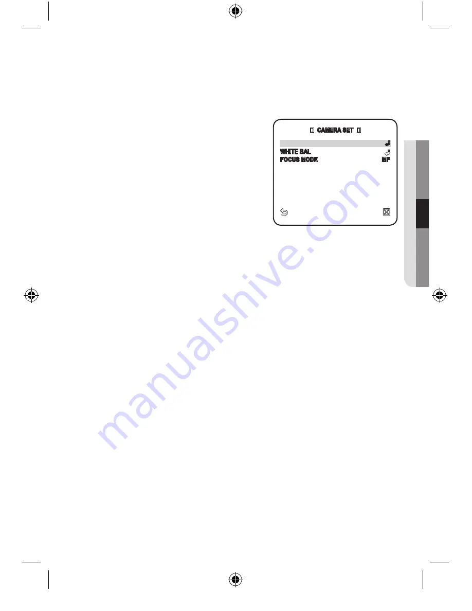
5.
6.
7.
M
CAMERA SET
IRIS
ALC
WHITE BAL
FOCUS MODE
MF
User Manual_SCC-C7455P_ENGLISH-139 39
2010-5-30 16:14:44


