Samsung Electronics-Contents may change without notice.
3-5
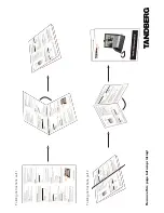
Installation
3-3-5 Cables
1. Connect the cradle and the hands-free box
with the data cable. See the figure 3-4.
2. Connect the antenna cable to the RF jack of
the cradle.
3. Connect the power cable as follows:
Connect the red wire to the battery (+) termi-
nal, black wire to the battery (-) terminal.
Then connect the orange wire to the switched
side of the ignition switch, and then connect
the brown wire to the stereo mute wire from
your vehicle stereo.
4. Connect the other end of the power cable to
the
PWR
jack of the hands-free box.
Notes:
¥ It is recommended to connect the power cable
directly to the battery to avoid power noise.
¥ Make sure the connection, in the vehicle,
between the battery (-) terminal and vehicle
chassis is made correctly.
¥ Make sure the fuse having a proper capacity is
used on the power cable.
¥ Make sure the cables do not pass over any sharp
metal edge that may damage it.
PWR
RED
3A FUSE
BAT.(+)
BAT.(-)
BLACK
IGN. Switch
ORANGE
STEREO Mute
BROWN
SAMSUNG
Figure 3-4 Cable Connections
Summary of Contents for SCH-211
Page 2: ...Samsung Electronics Co Ltd GH68 00335A ELECTRONICS ...
Page 3: ...Samsung Electronics Contents may change without notice 1 Specification ...
Page 5: ...Samsung Electronics Contents may change without notice 1 2 General Introduction MEMO ...
Page 11: ...Samsung Electronics Contents may change without notice 2 6 Specification MEMO ...
Page 17: ...Samsung Electronics Contents may change without notice 3 6 Installation MEMO ...
Page 47: ...Samsung Electronics Contents may change without notice 6 10 Troubleshooting MEMO ...
Page 65: ...Samsung Electronics Contents may change without notice 8 4 PCB Diagrams Bottom View ...
Page 93: ...Samsung Electronics Contents may change without notice 9 24 Electrical Parts List MEMO ...
Page 113: ...Samsung Electronics Contents may change without notice 10 20 Block Circuit Diagrams MEMO ...