PTZ CONTROLLER
User Guide
14
PTZ CONTROLLER
User Guide
15
■
AUTO : Turns the backlight off automatically if no
command has been entered in the last 30
seconds.
■
ON : Keeps the backlight on at all times.
■
OFF : Keeps the backlight off at all times.
■
Select RS-485 or RS-422.
■
Displays the current version of the controller firmware.
• To move between the options, move the joystick up or down.
• To change the value of the settings, move the joystick to the right or left.
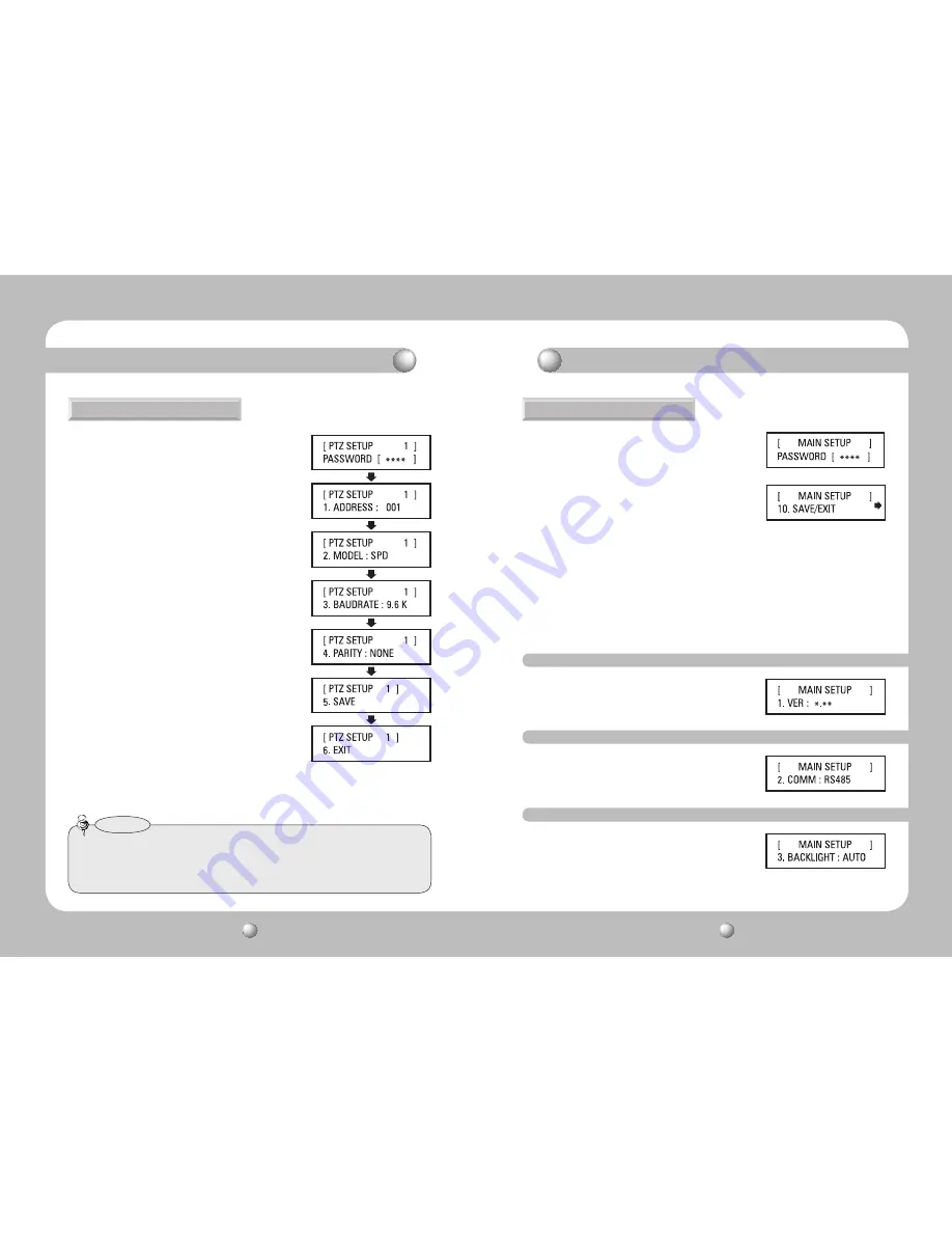
• For the default settings values, please refer to the picture on the right.
Setting Up Controller Environment
Setting Up Controller Environment
1. PTZ Setup
①
Press 1 on the number pad.
②
Hold down the SET button to enter the PTZ SETUP
mode.
③
Enter the 4-digit password. (Default Password: 0000)
④
To change a channel address, select a channel by
moving the joystick to the right or left. Or you can
enter the channel number and then press the ENT
button.
⑤
Change the Protocol, Baud Rate, and Parity Bit settings
of the select channel.
⑥
Select the SAVE menu to save the changes. You can
continue changing the settings by selecting different
channels. To exit to the initial screen, select the EXIT
menu or press the ESC button.
• To move between the options, move the joystick up or
down.
• To change the value of the settings, move the joystick
to the right or left.
• For the default settings values, please refer to the
picture on the right.
Protocol : Samsung Techwin SPD
Baud Rate : 9.6Kbps, Parity Bit : None
①
Press 2 on the number pad.
②
Hold down the SET button to enter the controller’s
MAIN SETUP mode.
③
Enter the 4-digit password. (Default Password: 0000)
④
After changing the settings, select <YES> in the
SAVE/EXIT menu to save the changes and move back
to the initial screen. To cancel changes and move
back to the initial screen, select <NO> in the Save
menu or press the ESC button.
• After changing the settings of a channel, you must select the Save menu. If you move to a different
channel without using the SAVE menu, the changes will not be saved.
• Under Controller Serial Setup, Data Bit is fixed to 8 and Stop Bit to 1. Serial values of the controller
and camera must match each other.
Notes
2. Controller Main Setup
2-1. Firmware Version
2-2. Serial Data Transfer Standard
2-3. LCD Backlight


