4-12
Disassembly and Reassembly
Samsung Electronics
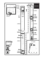
4-2-7 Loading Motor Ass’y, Pinch Review Ass’y
4-2-7(a) Disassembly
1) In unload mode, rotate the Pinch Review Ass’y
Œ
in a clockwise direction and left up the
Pinch Review Ass’y
Œ
.
2) De-solder the 2 points.
3) Remove the 1 screw
ˇ
and separate the 1 hook of
Loading Motor Ass’y
¨
.
4) Lift up the Loading Motor Ass’y
¨
.
4-2-7(b) Reassembly
1) Lock the one hook of Loading Motor Ass’y
¨
and
secure one screw
ˇ
.
2) Re-solder the 2 wires.
(+ into red wire , - into blue wire)
3) In disassembling position, insert the Pinch Review
Ass’y
Œ
and rotate the Pinch Review Ass’y
Œ
in
unload position.
3
4
2
SOLDER POINTS
LOADING MOTOR ASS'Y
¨
ˇ
1 SCREW
Œ
PINCH REVIEW ASS'Y
Fig. 4-17 Loading Motor Ass’y, Pinch Review Ass’y
Note : When disassembling and reassembling, be
careful not to touch the Pinch Roller
and the review post.
Summary of Contents for SC-D351
Page 8: ...Product Specification 2 4 Samsung Electronics MEMO ...
Page 24: ...3 16 Alignment and Adjustments Samsung Electronics MEMO ...
Page 58: ...Exploded View and Parts List 5 18 Samsung Electronics MEMO ...
Page 80: ...Wiring Diagram 8 2 Samsung Electronics MEMO ...
Page 82: ...PCB Diagrams 9 2 Samsung Electronics 9 1 Main PCB COMPONENT SIDE ...
Page 83: ...PCB Diagrams Samsung Electronics 9 3 CLK_41 85MHz Œ ˇ ˆ Ø Q708 Q707 Q706 Q704 Q703 Q702 Q701 ...
Page 84: ...PCB Diagrams 9 4 Samsung Electronics CONDUCTOR SIDE ...
Page 90: ...PCB Diagrams 9 10 Samsung Electronics 9 10 CVF PCB COMPONENT SIDE CONDUCTOR SIDE ...
Page 122: ...Operating Instructions 11 10 Samsung Electronics MEMO ...
Page 130: ...Troubleshooting 12 8 Samsung Electronics MEMO ...
Page 154: ...Reference Information 14 12 Samsung Electronics Loading state Unloading state Fig 14 11 ...
Page 164: ...Reference Information 14 22 Samsung Electronics Fig 14 16 LOADING POSTION UNLOADING POSTION ...


