background image

12

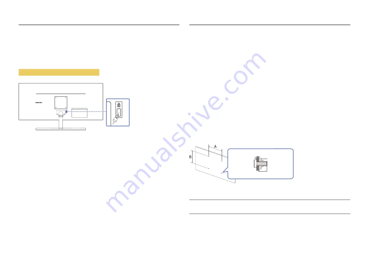
Anti-theft Lock


An anti-theft lock allows you to use the product securely even in public places.


The locking device shape and locking method depend on the manufacturer. Refer to the manuals provided 
with your anti-theft locking device for details.

To lock an anti-theft locking device:

Fix the cable of your anti-theft locking device to a heavy object such as a desk.

Put one end of the cable through the loop on the other end.

Insert the locking device into the anti-theft lock slot at the back of the product.

Lock the locking device.


An anti-theft locking device can be purchased separately.


Anti-theft locking devices can be purchased at electronics retailers or online.

Wall Mount Kit Specifications (VESA)


Install your wall mount on a solid wall perpendicular to the floor. Before attaching the wall mount to 
surfaces other than plaster board, please contact your nearest dealer for additional information. If you 
install the product on a slanted wall, it may fall and result in severe personal injury. Samsung wall mount 
kits contain a detailed installation manual and all parts necessary for assembly are provided.


Do not use screws that are longer than the standard length or do not comply with the VESA 
standard screw specifications. Screws that are too long may cause damage to the inside of the 
product.


For wall mounts that do not comply with the VESA standard screw specifications, the length of the 
screws may differ depending on the wall mount specifications.


Do not fasten the screws too firmly. This may damage the product or cause the product to fall, 
leading to personal injury. Samsung is not liable for these kinds of accidents.


Samsung is not liable for product damage or personal injury when a non-VESA or non-specified 
wall mount is used or the consumer fails to follow the product installation instructions.


Do not mount the product at more than a 15 degree tilt.


Standard dimensions for wall mount kits are shown in the table below.

C

Product

Wall mount bracket

Model name

VESA screw hole specs 
(A * B) in millimeters

C

Standard Screw

Quantity

S34C50*

100.0 x 100.0

6.0 ~ 8.0 mm

4.0

 mm Φ, 

0.7 pitch * 

6.0 ~ 8.0 mm long

4


Do not install your Wall Mount Kit while your product is turned on. It may result in personal injury due to 
electric shock.

Summary of Contents for S34C500GAE

Page 1: ...contents of this manual are subject to change without notice to improve quality Samsung Samsung owns the copyright for this manual Use or reproduction of this manual in parts or entirety without the a...

Page 2: ...2 Menu Picture 20 Eye Care 24 PIP PBP 24 OnScreen Display 26 System 27 Support 30 Installing the Software Easy Setting Box 31 Restrictions and Problems with the Installation 31 System Requirements 31...

Page 3: ...oduct damage caused by customer s fault 39 Others 39 FreeSync 40 Troubleshooting Guide Requirements Before Contacting Samsung CustomerService Centre 32 Product diagnosis Screen issue 32 Checking the R...

Page 4: ...o protective earth ground Caution Consult instructions for use This symbol instructs the user to consult the user manual for further safety related information Electricity and Safety Warning Do not us...

Page 5: ...product away from oil pollution And do not install or use the product in the kitchen or near the kitchen stove Caution Do not drop the product while moving Do not set down the product on its front Whe...

Page 6: ...hunderstorm power off the product and remove the power cable Do not drop objects on the product or apply impact Do not move the product by pulling the power cord or any cable If a gas leakage is found...

Page 7: ...may get stuck and injured Tilting the product at an excessive angle may cause the product to fall and an injury may result Do not place heavy objects on the product Product failure or personal injury...

Page 8: ...front of the screen Adjust the angle so light does not reflect on the screen Keep your forearms perpendicular to your upper arms and level with the back of your hands Keep your elbows at about a right...

Page 9: ...nto the stand neck as the direction shown in the figure Check that the stand neck is firmly connected Tightly fasten the connecting screw at the bottom of the stand base Fasten the large screw in the...

Page 10: ...by the stand Do not press down on the product There is a risk of damaging the product Checking the space around the product Make sure to have enough space forventilation when placing the product An in...

Page 11: ...product tilt can be adjusted Hold the lower part of the product and adjust the tilt carefully Caution After adjusting the product tilt if the screen is not level take the following actions 1 1 Hold t...

Page 12: ...unt kits contain a detailed installation manual and all parts necessary for assembly are provided Do not use screws that are longer than the standard length or do not comply with the VESA standard scr...

Page 13: ...ess the 5 Way Button when the screen is turned on Custom Key Custom Key is used to directly access the function set in Setup Custom Key Go to System Setup Custom Key and change the custom key Source C...

Page 14: ...ged Eye Saver Mode Volume Source Eye Saver Mode Off Features The Direct Key Guide screen shows if Eye SaverMode is enabled Off Low High When the product not displays the OSD menu the 5 Way Button coul...

Page 15: ...bles from both the product and the external device to prevent damage to the product due to a short circuit or over current 3 After all signal cables have been properly connected connect the power cabl...

Page 16: ...s are subject to change without notice to improve quality Refer to the actual product Port Description SERVICE Connect to a USB device Used to update the software Connects to a source device using an...

Page 17: ...s If you use a unauthorized HDMI cable the image quality may be degrade Connection Using an HDMI DVI Cable When using HDMI DVI cable audio may not be supported according to source device The optimum r...

Page 18: ...the power cable to the power outlet 3 Press the 5 Way Button at the bottom of the product to turn it on The input voltage is switched automatically Tidying Up the Connected Cables 1 1 2 Connect the co...

Page 19: ...s turned off and on again If you want to set the optimum resolution foryour computer Please refer to Q A How can I change the resolution List of graphic cards supporting HDR10 HDR10 is accessible only...

Page 20: ...e for the environment where the product will be used This menu is not available when Eco Saving Plus is enabled This menu is not available when Game Mode is enabled This menu is not available when Eye...

Page 21: ...ou can adjust the general brightness of the picture Range 0 100 A highervalue will make the picture appear brighter This menu is not available when Eco Saving Plus is enabled This menu is not availabl...

Page 22: ...menu is not available when PIP PBP Mode is enabled Contrast Enhancer Automatically balance the contrast to prevent excessive differences between bright and dark areas Black Level If a DVD player or se...

Page 23: ...3 16 9 21 9 Screen Fit The function may not be supported depending on the ports provided with the product Changing the Screen Ratio is available when the following conditions are satisfied The input...

Page 24: ...e is set to On Eye SaverMode Set to an optimum picture quality suitable for eye relaxation PIP PBP 2nd 3rd Description PIP PBP Mode Turn PIP PBP Mode on or off Mode Type Select the size and aspect rat...

Page 25: ...ot be supported depending on the ports provided with the product Changing the Screen Ratio is available when the following conditions are satisfied The input source is 480p 576p 720p or1080p and produ...

Page 26: ...position up or down Language Set the menu language A change to the language setting will only be applied to the onscreen menu display Display Time Set how long the menu window will remain on screen fo...

Page 27: ...d by the monitor panel Off Deactivate the Eco Saving Plus function Auto The power consumption will automatically be reduced by about 10 over the current setting The reduction of power consumption depe...

Page 28: ...e product will automatically power off after the specified time has elapsed This option is only available when Eco Timer is set to On PC AV Mode Set PC AV Mode to AV The picture size will be enlarged...

Page 29: ...er part of the product Working The power LED is on when the product is turned on Stand by The power LED is on when the product is turned off Accessibility Configures the accessibility options High Con...

Page 30: ...t only one BIN file bin is saved in the root directory If the No USB devices detected Please check and try again message is displayed this is probably due to the following reasons A USB device is not...

Page 31: ...ications If the shortcut icon does not appear press the F5 key Restrictions and Problems with the Installation The Easy Setting Box installation may be affected by the Graphics Card Motherboard and th...

Page 32: ...following Caution When the product makes popping cracking sound The sound may be caused by contraction or expansion from temperature change of external components or internal circuit of the product Th...

Page 33: ...nsion cable etc and try again Set the resolution and frequency to the recommended level The screen appears unstable and shaky There are shadows or ghost images left on the screen Check that the resolu...

Page 34: ...the volume is still low after turning it up to the maximum level adjust the volume on your PC sound card or software programme Video is available but there is no sound Sound cannot be heard if an HDM...

Page 35: ...n refresh rate under Monitorsettings How can I change the resolution Windows 7 Go to Control Panel Appearance and Personalization Display Screen Resolution Adjust Resolution Windows 8 Windows 8 1 Go t...

Page 36: ...45 C 4 F 113 F Humidity 5 95 non condensing Plug and Play This product can be installed and used with any Plug and Play compatible systems Two way data exchange between the product and PC system optim...

Page 37: ...er LED turns on In such a case change the settings according to the following table by referring to the graphics card user manual Resolution Horizontal Frequency kHz Vertical Frequency Hz Pixel Clock...

Page 38: ...eft to the right side of the screen is called a horizontal cycle The reciprocal number of a horizontal cycle is called horizontal frequency Horizontal frequency is measured in kHz Vertical Frequency R...

Page 39: ...gramme If customer requests software installation and setup for the product If a service technician removes cleans dusts or foreign materials inside of the product If customer requests an installation...

Page 40: ...to variation of the output frequency from the graphics card The response rate during the game may fluctuate depending on the resolution A higher resolution generally decreases the response rate The s...

Reviews: