background image

7

Your New Plasma Display Panel 

(continued)

ENG

The actual configuration on your PDP may be different, 
depending on your model.
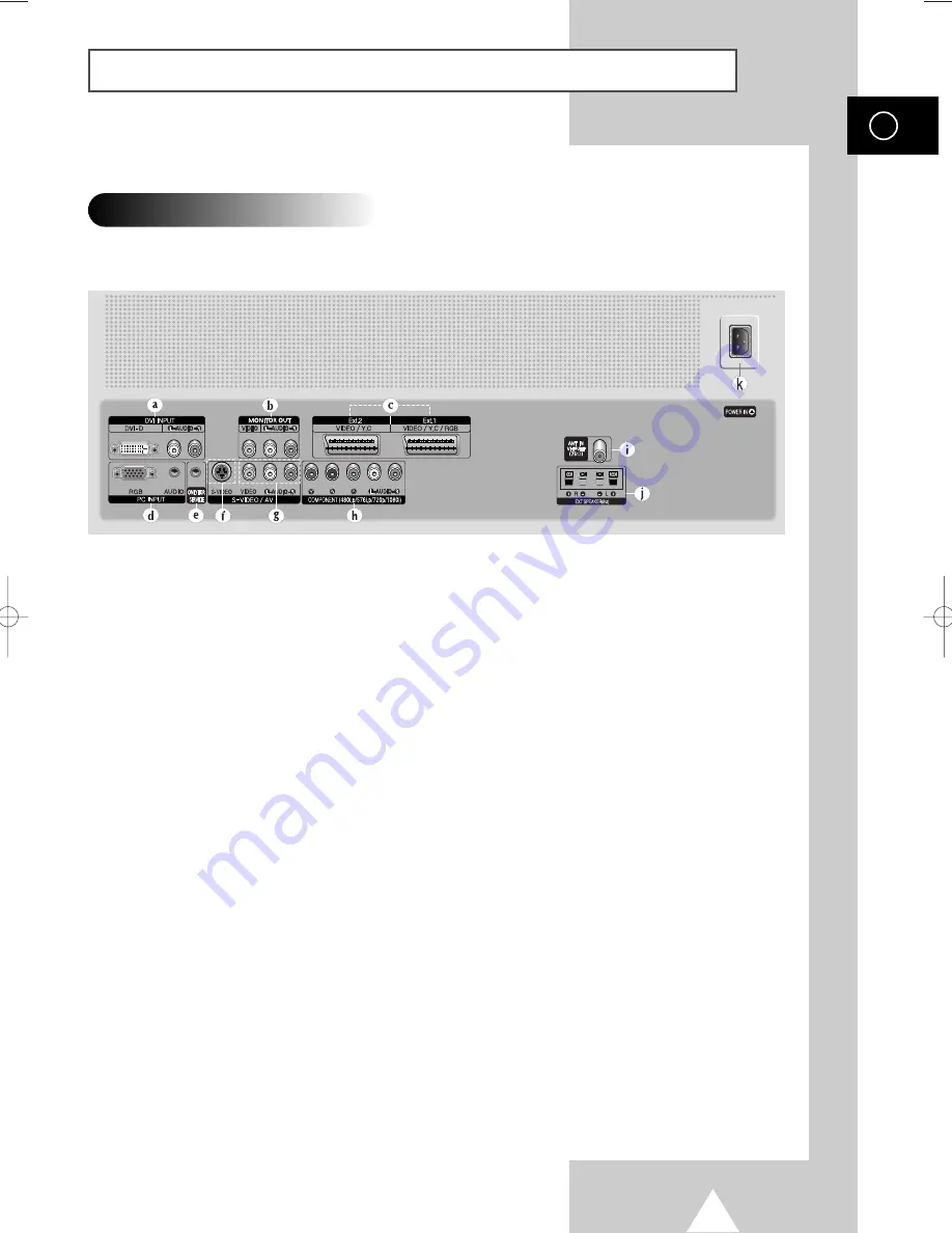
Rear Panel

For further details about connection, refer to pages 52~56.

a) DVI INPUT

Connect to digital video output jack for device
with DVI output.

b) MONITOR OUT (VIDEO

L-AUDIO-R)

Outputs for external devices

c) Ext.1,  Ext.2

Inputs or outputs for external devices, such as
VCR, DVD, video game device or video disc
players.

d) PC INPUT (RGB IN / AUDIO)

Connect to the video and audio output jack on
your PC. 

e) ONLY FOR SERVICE

Connector for service only.

f) S-VIDEO

Video and audio inputs for external devices with
an S-Video output, such as a camcorder or VCR.

g) AV (VIDEO / L-AUDIO-R )

Video and audio inputs for external devices, such
as a camcorder or VCR.

h) COMPONENT 

Video (

Y/P

b

/P

r

) and audio (

L-AUDIO-R

) inputs for

Component.

i) ANT IN VHF/UHF (75

)

75

Coaxial connector for Aerial/Cable Network.

j) EXT SPEAKER(8

)

Connectors for external speakers.

K) POWER IN

Connect the supplied power cord.

BN68-00699A-00_Eng  4/13/04  11:17 AM  Page 7

Summary of Contents for PS-42D4S

Page 1: ...PDP TELEVISION PLASMADISPLAYPANEL Owner s Instructions Before operating the unit please read this manual thoroughly and retain it for future reference ON SCREEN MENUS PICTURE IN PICTURE PIP TELETEXT ...

Page 2: ...ss and contrast of this screen when displaying a still image Cell Defect The plasma display panel consists of fine cells Although the panels are produced with more than 99 9 percent active cells there may be some cells that do not produce light or remain lit Height The PDP can normally operate only under 2000m in height It might abnormally function at a place over 2000m in height and do not instal...

Page 3: ...rts Owner s Instructions Remote Control AAA Batteries Power Cord S VIDEO Cable PC Cable DVI Cable Antenna Cable Ferrite Core for Speaker Wire Speaker Wires Scart Cable PC Audio Cable Component Cables RCA Sold Separately ...

Page 4: ...ls Automatically 19 Storing Channels Manually 20 Skipping Unwanted Channels 22 Sorting the Stored Channels 23 Assigning Names to Channels 24 Activating the Child Lock 25 Displaying Information 26 Using the LNA Low Noise Amplifier Feature 38 USING YOUR DISPLAY continued Changing the Picture Standard 26 Adjusting the Picture Settings 27 Adjusting the Picture Settings PC or DVI Mode 28 Setting the Pi...

Page 5: ...External Output 47 USING THE TELETEXT FEATURE Teletext Feature 48 Displaying the Teletext Information 49 Selecting Display Options 50 Selecting a Teletext Page 51 ADDITIONAL INFORMATION AND CONNECTIONS Connecting to the External Devices 52 Connecting to the S Video Input 53 Connecting to the DVI Input 54 Connecting to the PC Input 54 Connecting to the Component Input 55 Connecting and Using the Ho...

Page 6: ...ion When the Main menu is displayed on screen the Main menu is not operated with source key MENU Menu display and exit Volume adjustment C P Channel selection Auto power On I Press to turn the PDP on and off a Power Indicator Power Off Red Power On Off Timer On Green Remote Control Signal Receiver Aim the remote control towards this spot on the PDP b a b ...

Page 7: ...R DVD video game device or video disc players d PC INPUT RGB IN AUDIO Connect to the video and audio output jack on your PC e ONLY FOR SERVICE Connector for service only f S VIDEO Video and audio inputs for external devices with an S Video output such as a camcorder or VCR g AV VIDEO L AUDIO R Video and audio inputs for external devices such as a camcorder or VCR h COMPONENT Video Y Pb Pr and audi...

Page 8: ... BOTH TELETEXT INFORMATION AND THE NORMAL BROADCAST INFORMATION DISPLAY TELETEXT REVEAL TV MODE SELECTION EXIT TELETEXT DEPENDING ON THE MODEL DIRECT CHANNEL SELECTION PRESS TO SELECT ALL OF THE AVAILABLE VIDEO SOURCES TELETEXT MODE LIST FLOF SELECTION DEPENDING ON THE MODEL CONFIRM YOUR CHOICE STORE OR ENTER NEXT CHANNEL TELETEXT NEXT PAGE PICTURE SIZE TELETEXT SIZE SELECTION PICTURE EFFECT SELEC...

Page 9: ...inst on the remote control on the battery against on the remote control 3 Replace the cover by aligning it with the base of the remote control and pressing it back into place Inserting the Batteries in the Remote Control Assembling the Stand Base 1 Assemble two support pins with the stand base and firmly secure both sides of the support pins using 8 screws provided 2 Assemble the PDP with the stan...

Page 10: ...e adjusted from 0 to 15 by 2 The wall mount bracket is delivered separately Please tighten the captive screw in the direction of the arrow after assembling the bracket Installation Notes Do not install the PDP on any place other than vertical walls To protect the performance of the PDP and prevent troubles avoid the followings Do not install next to smoke and fire detectors Do not install in an ar...

Page 11: ...t to the wall to avoid injury from a falling PDP Connecting External Devices to the PDP 1 Be sure to remove the safety pins underneath the PDP If the safety pins are not removed the angle cannot be adjusted Any attempt to do so may cause damage to the PDP 2 Pull out the bottom of the PDP which has been attached to the Wall Mount Bracket in the direction indicated by the arrows refer to the illustr...

Page 12: ...holes on the rear of the PDP 3 Tighten the PDP and the speaker bracket using the screws removed from the PDP When moving your PDP do NOT hold the speaker connected to your PDP It may damage the bracket clamping the speaker and your PDP together and result in a drop of your PDP and a risk of personal damage and injury ...

Page 13: ... power handling capability of 10 watts minimum impedance 8Ω When you connect the speaker wire to the external speaker out connector first bind the speaker wire round the ferrite core to secure it Before connecting the speaker wire to the PDP turn off your PDP Ferrite Cores The ferrite cores are used to attenuate undesired signals When connecting cables attach one of these ferrite cores to the cabl...

Page 14: ...evision channels correctly a signal must be received by the set from one of the following sources An outdoor aerial A cable television network A satellite network 1 In the first three cases connect the aerial or network input cable to the 75Ω coaxial socket on the rear of the PDP 2 If you are using an indoor aerial you may need to turn it when tuning your PDP until you obtain a picture that is bot...

Page 15: ...ar picture appears Refer to Storing Channels Automatically on page 19 or Storing Channels Manually on page 20 3 To switch your PDP off press the I button again Your PDP can be placed in Standby mode in order to reduce the Power consumption The Standby mode can be useful when you wish to interrupt viewing temporarily during a meal for example 1 Press the POWER button on the remote control Result Th...

Page 16: ...d immediately after the first Failure to do this will result in a single digit channel being displayed SLEEP Used to select a preset time interval off 30 60 90 120 150 180 Used to increase the volume Used to decrease the volume MUTE Used to switch the sound off temporarily To turn the sound back on press this button again or press the or button MENU Used to display the Used to return to the previo...

Page 17: ...the search press the ENTER button Result The search will end automatically Channels are sorted and stored in an order which reflects their position in the frequency range with lowest first and highest last When it has finished the Clock Set menu is displayed To stop the search before it has finished or return to normal viewing press the MENU button 8 Press the ENTER button to set the Clock Press t...

Page 18: ...button Result The main menu is displayed 2 Press the or button to select Setup Result The options available in the Setup group are displayed 3 Press the ENTER button 4 Press the or button to select Language Press the ENTER button Result The languages available are listed 5 Select the appropriate language by pressing the or button 6 Press the ENTER button to confirm your choice 7 When you are satis...

Page 19: ...s the ENTER button 4 Press the or button to select Country Press the ENTER button Result The countries available are listed 5 Select your country or area by pressing the or button If you have selected the Others option but do not wish to scan the PAL frequency range store the channels manually see page 21 6 Press the ENTER button to confirm your choice 7 Press the or button to select Auto Store Pr...

Page 20: ...ct the broadcasting standard required Press the œ or button to select Colour System and press the or button The colour standards are displayed in the following order depending on the model Auto PAL SECAM or Auto NT3 58 NT4 43 PAL60 6 Press the œ or button to select Sound System and press the or button The sound standards are displayed in the following order depending on the model BG DK I L Country...

Page 21: ...ess the or button until you find the correct number 10 To store the channel and associated programme number select the Store by pressing the œ or button Press the ENTER button 11 Repeat Steps 7 to 10 for each channel to be stored Channel mode C Real channel mode You can select a channel by entering the assigned number to each air broadcasting station in this mode S Cable channel mode You can selec...

Page 22: ...dit Press the ENTER button Result The Edit menu is displayed 5 Press the or button to select Add Delete Press the ENTER button Result The Add Delete menu is displayed with the current channel automatically is selected 6 Press the or button to select the channel to be deleted 7 Press the ENTER button 8 To add or delete the channel select Added or Deleted by pressing the or button Press the ENTER bu...

Page 23: ...n to select Sort Press the ENTER button Result The Sort menu is displayed 6 Select the channel that you wish to move by pressing the or button Press the ENTER button 7 Select the number of the programme to which the channel is to be moved by pressing the or button Press the ENTER button Result The channel is moved to its new position and all other channels are shifted accordingly 8 Repeat Steps 6 ...

Page 24: ...he current channel automatically is selected 6 If necessary select the channel to be assigned a new name by pressing the or button Press the ENTER button Result Arrow indications are displayed around the name box 7 Press the or button to select a letter A Z a number 0 9 or a symbol space Move on the previous or next letter by pressing the œ or button 8 When you have finished entering the name pres...

Page 25: ...on Result The Child Lock menu is displayed with the current channel automatically is selected Blue Screen is displayed when the Child Lock is activated 6 Press the or button to select the channel to be locked 7 Press the ENTER button To lock the channel select Locked by pressing the or button to unlock the channel select Unlocked Press the ENTER button to confirm Activating the Child Lock Country ...

Page 26: ...available depending on the input source Dynamic Standard Movie Custom High Middle Low Custom PC or DVI Mode 6 Press the ENTER button to confirm You can also set these options simply by pressing the P MODE Picture Mode button Changing the Picture Standard You can view the channel information and setting status you select by pressing the INFO button on the remote control P 1 Picture Dynamic Sound Mu...

Page 27: ... s cursor left or right by pressing the œ or button When the Picture Mode is set to Custom the settings values may vary depending on the input source ex RF Video Component PC or DVI If you make any changes to these settings the picture standard is automatically switched to the Custom Colour Tone Cool2 Cool1 Normal Warm1 Warm2 7 When you are satisfied with the settings press the EXIT button to retu...

Page 28: ...ly Colour1 Colour2 Colour3 10 Press the MENU button Result The options available in the Picture group are displayed again 11 Press the or button to select Colour Control Press the ENTER button Result The Colour Control menu is displayed 12 Press the or button to select the option R G B to be adjusted Press the ENTER button Result The horizontal bar is displayed Move the horizontal bar s cursor lef...

Page 29: ...on Adjust for best picture 7 Press the MENU button to confirm your choice 8 Press the MENU button Result The options available in the PC Setup group are displayed again 9 Press the or button to select Position Press the ENTER button Result The options available in the Position group are displayed 10 Adjust the position by using the œ or button 11 Press the MENU button to confirm your choice Settin...

Page 30: ...re displayed 13 Press the MENU button Result The options available in the PC Setup group are displayed again 14 Press the or button to select Auto Adjustment Press the ENTER button Result The screen quality and position are automatically reset with the Auto Adjusting displayed 15 When you are satisfied with the settings press the MENU button repeatedly to return to the normal viewing Resolution 10...

Page 31: ...ch the required setting 5 Press the œ or button until the picture and sound are both clear and sharp If you are unable to fine tune a channel check that the Colour System and Sound System settings are correct Fine tune Store will change the colour of the Channel OSD On Screen Display from White to Red To reset the fine tuning to 0 press the button to select Reset then press the ENTER button P 1 0 ...

Page 32: ...e ENTER button Result You can view every memorized channel in order P 1 Ch Scan Return You can freeze the picture when watching a television programme simply by pressing the STILL button To return to normal viewing press it again In the PIP mode the main and sub pictures are stilled at the same time This function will automatically cancel after 5 minutes Freezing the Current Picture Country Austri...

Page 33: ...o confirm You can select these options by simply pressing the P SIZE button on the remote control The picture size can not be changed in the PIP mode Depending on the input source the P SIZE options may vary Positioning and Sizing the screen using Zoom Resizing the screen using the Zoom enables the positioning and sizing of the screen to up down direction using the or button as well as the screen ...

Page 34: ...e Off Size 16 9 DNIe On PIP Picture Move Enter Return TV On Off Demo You can automatically sense and process film signals from some sources and adjust the picture for optimum quality 1 Press the MENU button Result The main menu is displayed 2 Press the or button to select Picture Result The options available in the Picture group are displayed 3 Press the ENTER button 4 Press the or button to selec...

Page 35: ...f the Blue Screen Setting Setting the Blue Screen Time Language English AV Setup Digital NR On Miscellaneous PC Setup Setup Move Enter Return Melody Off Plug Play Blue Screen Off Miscellaneous Move Enter Return TV A melody sounds when the television is powered on or off 1 Press the MENU button Result The main menu is displayed 2 Press the or button to select Setup Result The options available in t...

Page 36: ...sult The main picture and sub picture are interchanged 8 Press the or button to select Size Select a size of the sub picture by pressing the ENTER button Result The sizes are displayed in the following order Large Small Double1 Double2 Select a size of the sub picture by pressing the or button Press the ENTER button Table of PIP Settings Viewing the Picture In Picture PIP PIP PIP On Source TV Swap...

Page 37: ...at you want to view through sub picture by pressing the ENTER button If the sub picture is no signal and the main picture is output from a Component PC or DVI signal the sub picture will be blue If the main picture is output from a Video signal the sub picture will be black Viewing the Picture In Picture PIP continued PIP PIP On Source TV Swap Size Position Prog P08 TV Move Enter Return PIP PIP On...

Page 38: ...t Fine Tune Ch Scan Channel Move Enter Return TV Add Delete Sort Name LNA Off Child Lock Edit Move Enter Return TV Add Delete Sort Name LNA Off Child Lock Edit Move Enter Return TV This function is very useful in the situation that the TV is used in weak signal LNA amplifies the TV signal in the weak signal area but not noise 1 Press the MENU button Result The main menu is displayed 2 Press the or...

Page 39: ... is selected 4 Press the ENTER button again 5 Select the option by pressing the or button The sound effects are displayed in the following order Standard Music Movie Speech Custom 6 Press the ENTER button to confirm You can also set these options simply by pressing the S MODE Sound Mode button Mode Standard Equalizer Auto Volume Off SRS TSXT Off Internal Mute Off Sound Move Enter Return TV Mode St...

Page 40: ...ode Standard Equalizer Auto Volume Off SRS TSXT Off Internal Mute Off Sound Move Enter Return TV Off On The sound settings can be adjusted to suit your personal preferences 1 Press the MENU button Result The main menu is displayed 2 Press the or button to select Sound Result The options available in the Sound group are displayed 3 Press the ENTER button 4 Press the or button to select Equalizer Pr...

Page 41: ...rround XT technology is incorporated under license from SRS Labs Inc Setting the TruSurround XT If you want to hear the sound through separate speakers cancel the internal amplifier 1 Press the MENU button Result The main menu is displayed 2 Press the or button to select Sound Result The options available in the Sound group are displayed 3 Press the ENTER button 4 Press the or button to select Int...

Page 42: ... the Mono When receiving a mono sound in the AV mode connect to the AUDIO L input connector on the side of the television If the mono sound comes out only from left speaker press the Dual I II button Type of broadcast Regular broadcast Standard audio Regular NICAM Mono NICAM Stereo NICAM Dual I II Regular broadcast Standard audio Bilingual or Dual I II Stereo On screen indication Mono Normal use N...

Page 43: ...the preset time intervals Off 30 60 90 120 150 180 by pressing the or button Press the œ or button to move to the Activation 7 When you are satisfied with the settings select Activation to Yes or No by pressing the or button 8 Press the ENTER button to confirm your selection You can also set these options simply by pressing the SLEEP button If the sleep timer is not yet set Off is displayed If the...

Page 44: ...t of the television the clock setting will be reset 1 Press the MENU button Result The main menu is displayed 2 Press the or button to select Setup Result The options available in the Setup group are displayed 3 Press the ENTER button 4 Press the or button to select Time Press the ENTER button Result The options available in the Time group are displayed with Clock is selected 5 Press the ENTER but...

Page 45: ... button to select Time Press the ENTER button Result The options available in the Time group are displayed 5 Press the or button to select On Timer Press the ENTER button Result The options available in the On Timer group are displayed 6 Select the Hour Min Prog Volume by pressing the œ or button Set these by pressing the or button 7 When you are satisfied with the settings select Activation to Ye...

Page 46: ...7 Press the or button to select Edit Name Press the ENTER button Result The options available in the Edit Name group are displayed 8 Press the or button to select external device Ext 1 Ext 2 AV S Video Component PC DVI 9 Press the ENTER button Result The Edit Name available are listed 10 Select the name by pressing the or button Press the ENTER button 11 Set other signal sources VCR DVD Cable STB ...

Page 47: ...deo signals are output to the external connector 1 Press the MENU button Result The main menu is displayed 2 Press the or button to select Setup Result The options available in the Setup group are displayed 3 Press the ENTER button 4 Press the or button to select AV Setup Press the ENTER button Result The AV Setup menu is displayed 5 Press the or button to select required input Ext 2 then press th...

Page 48: ...to numbered pages see diagram Part Contents A Selected page number B Broadcasting channel identity C Current page number or search indications D Date and time E Text F Status information FASTEXT information Teletext information is often divided between several pages displayed in sequence which can be accessed by Entering the page number Selecting a title in a list Selecting a coloured heading FAST...

Page 49: ... or button 2 Press the TTX MIX button to activate the teletext mode Result The contents page is displayed It can be redisplayed at any time by pressing the index button 3 Press the TTX MIX button again Result The screen will be split into two This Double Teletext feature lets you view the actual broadcast and teletext information separately on the screen 4 If you wish to display the actual broadca...

Page 50: ... to quiz games for example The normal screen reveal again A secondary page by entering its number sub page The broadcast when searching for a page cancel The next page page up The previous page page down Double size letters in the size Upper half of the screen Once Lower half of the screen Twice The normal screen Three times Selecting Display Options ...

Page 51: ...oadcasting company the different topics covered on a Teletext page are colour coded and can be selected by pressing the coloured buttons on the remote control Press the coloured button corresponding to the topic that you wish to select the available topics are given on the status line Result The page is displayed with other coloured information that can be selected in the same way 3 To display the...

Page 52: ... end can be fitted with A SCART connector Three RCA connectors VIDEO AUDIO L R or VCR Decoder Video game device Video disc player Satellite receiver DVD Rear of the TV Input Output Camcorder Video disc player Video game device Input Output Specification Connector Input Output Video Audio L R S Video RGB Video Audio L R Ext 1 Only TV output is available Ext 2 Output you can choose ...

Page 53: ...or VCR Rear of the TV Camcorder VCR To play picture and sound both the S VIDEO and RCA connectors must be used and Whenever you connect an audio or video system to your television ensure that all elements are switched off Refer to the documentation supplied with your equipment for detailed connection instructions and associated safety precautions ...

Page 54: ...ng to the PC Input The RGB video and AUDIO connectors are used for interfacing with your PC Personal Computer and Rear of the TV The DVI video and L AUDIO R connectors are used for equipment with a DVI output Personal Computer Rear of the TV and ...

Page 55: ...55 ENG Connecting to the Component Input The COMPONENT connectors are used for DTV receiver or DVD 480i p 576i p 720p 1080i DVD Rear of the TV DTV receiver or ...

Page 56: ... Be sure to connect the video cable properly if desired external input Ext 1 or Ext 2 cannot be selected Play the DVD after activating the DVD Home Theater System Use the volume control of the Home Theater System while watching the PDP using the DVD Home Theater where the PDP TV does not produce the audio DVD Home Theater Rear of the TV AV Receiver Amplifier Use the Monitor Out ports of the PDP fo...

Page 57: ... the following sequence Start Settings Control Panel When the control panel screen appears click on Display and a display dialog box will appear Select the Settings tab in the display dialog box The two key variables that apply the television PC interface are Resolution and Colours The correct settings for these two variables are Size sometimes called Resolution 640 x 480 pixels PS42D4S Colour 24 ...

Page 58: ...TV VIDEO button to enter the Video mode Also make sure that the PC is connected When connecting a notebook PC to the television make sure that the PC screen is displayed through only the television Otherwise random signals might appear When horizontal synchronous signals seem irregular in PC mode check PC power saving mode or cable connections The Display Settings Table above complies to the IBM V...

Page 59: ...inance input 21 Screening chassis return SCART Connector Ext1 Ext2 Pin PC IN 1 Red R 2 Green G 3 Blue B 4 Grounding 5 Grounding DDC 6 Red R Grounding 7 Green G Grounding 8 Blue B Grounding 9 Reserved 10 Sync Grounding 11 Grounding 12 Data DDC 13 Horizontal sync 14 Vertical sync 15 Clock DDC PC Input Connector 15Pin Pin Signal 1 T M D S Data2 2 T M D S Data2 3 T M D S Data2 4 Shield 4 T M D S Data4...

Page 60: ...as been pressed Adjust the colour settings Check that the broadcast system selected is correct Try to identify the electrical appliance that is affecting the television then move it further away Plug your television into a different mains socket Check the direction location and connections of your aerial This interference often occurs due to the use of an indoor aerial Replace the remote control b...

Page 61: ...61 ENG Memo ...

Page 62: ...ELECTRONICS AFTER SALES SERVICE Do not hesitate to contact your retailer or service agent if a change in the performance of your product indicates that a faulty condition may be present BN68 00699A 00 ...

Reviews: