Connecting a wired remote controller
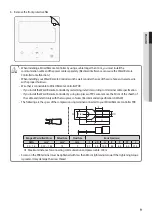
1. Connect 'F3, F4' of TB-C kit with 'F3, F4' of a wired remote controller.
f
2 units (wired remote controllers) are able to be installed on TB-C.
f
When 2 units are installed, either one shall has "Master" setting and another one shall have "Slave" settings on a wired
remote controller.
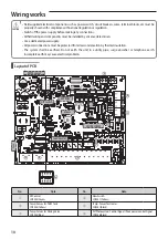
Temp. Sensor for DHW, Backup heater and a Water Flow Sensor
Relay
External wiring to control a switch of relay by a installer
Temp. sensor for DHW
Flow Sensor
Temp. sensor for backup heater
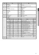
Connecting a temp. sensor wire into DHW
1. Put the sensor side of a temp. sensor wire into the designated location in a DHW.
2. Connect the other side of the line at CNS042.
Connecting a temp. sensor wire to outlet of backup heater
1. Put the sensor side of a temp. sensor wire into the designated location in a backup heater.
2. Connect the other side of the line at CNS047.
Connecting a flow sensor
1. Install a flow sensor in water line.
2. Connect a wire a flow sensor into 'CNS057' connector.
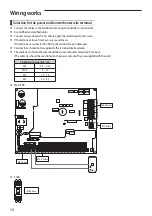
Connecting a PV(Photovoltaic) Signal / Peak power control Signal
1. Install as above diagram.
2. Connect the PV / Peak power control signal wire to the 'CNS046' connector.
• It operates according to the setting of FSV, and both functions can not be used at the same time.
(PV Control / Peak power control)
NOTE
19
ENGLISH

