20
DISASSEMBLY AND REASSEMBLY
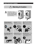
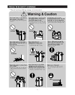
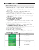
3-1) Caution On Disassembly
●
When replacing or repairing electric components, unplug power cord before you replace or repair.
→
Be careful of electric shock
●
When replacing electric components, use a regular component.
→
Be sure to check the indications like the model number, rating voltage, rating current, operation
temperature etc..
●
When repairing, the wiring of harness should be free from water infiltration and firm.
→
When applying force, the harness shouldn’t be detached.
●
When repairing, completely remove dust and foreign substances from housing, wiring, joint etc..
→
Prevents fire due to tracking or short.
●
Check if water came into electric components.
→
If there is a sign of water infiltration, replace the component and take necessary action like
insulation tapping etc..
●
Check the assembly of the component after repairing.
→
Maintain the same status as that before repairing.
●
Check the using environment of the refrigerator.
→
If the installation is made unstably or the machine is installed in humid conditions or water,
change its location.
●
If grounding seems necessary, ground it.
→
If there is risk of short-circuit due to water or humid conditions, be sure to earth.
●
Do not plug several devices in one socket.
●
Check for breakage, press, scratch, deterioration etc. of power plug and power consent.
→
Immediately repair if the power plug or power consent is defective.
→
When moving the product, be careful not to get scratch or pressed due to surrounding objects.
●
Do not store food unstably or do not store bottles in the freezer.
●
Do not let consumer repair the machine personally.
●
Do not store other materials except food in the refrigerator.
→
Medicine, chemical sample and etc. : Home refrigerator cannot maintain precise temperature.
→
Highly flammable material (alcohol, benzene, ether, LP gas, butane gas etc.) : explosive.
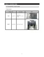
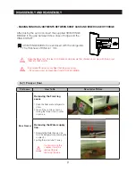
- TOOLS REQUIRED FOR DISASSEMBLY
IMAGE
ITEM
(+) SCREW DRIVER
(-) SCREW DRIVER
(-) SMALL SCREW DRIVER
SOCKET WRENCH
Summary of Contents for LS3165H52HR
Page 52: ...54 TROUBLESHOOTING Diode Voltage of IPM ...
Page 69: ...72 PCB DIAGRAM 6 3 Connector Arrangement Main Board ...
Page 71: ...69 5 WIRING DIAGRAM ...
Page 72: ...74 7 1 Block Diagram 7 SCHEMATIC DIAGRAM ...
Page 73: ...75 SCHEMATIC DIAGRAM 7 2 Block Diagram INVERTER PBA DC 13 2V 5V ...
Page 76: ...EXPLODED VIEW 1 FREEZER ...
Page 78: ...15 EXPLODED VIEW 2 FRIDGE 16 ...
Page 83: ...1 7 1 8 4 5 7 3 8 2 8 3 11 10 12 EXPLODED VIEW 4 DOOR FRE 4 6 9 3 13 ...
Page 85: ...3 4 5 1 3 2 2 3 3 3 4 3 4 1 3 1 6 EXPLODED VIEW 5 DOOR REF IN ...
Page 87: ...3 3 1 2 1 1 1 4 1 5 1 6 1 7 4 EXPLODED VIEW 6 DOOR REF OUT 1 ...

