background image

SIDE BY SIDE

               BASIC : RH25H561*

,

L

S

3

1

6

5

H

5

2

H

R

 ,

R

S

1

1

6

5

H

5

2

H

 :


E

M

A

N


L

E

D

O

M

 ,

Z

B

/

L

S

3

1

6

5

H

5

2

H

R

 ,

P

A

/

L

S

3

1

6

5

H

5

2

H

R

 ,

A

A

/

R

S

1

1

6

5

H

5

2

H

 :


E

D

O

C


L

E

D

O

M

RH25H5613SL/EY, RH25H5613SL/EM, RH25H5613SL/CL, 

RH25H5613SL/PE, RH25H5613SL/BG, RH25H5613SL/ZS

REFRIGERATOR

REFRIGERATOR

CONTENTS

1. PRECAUTIONS(SAFETY WARNINGS)

  ···············

5

2. PRODUCT SPECIFICATIONS

  ······································

8

3. DISASSEMBLY AND REASSEMBLY

  ················

19

4. TROUBLESHOOTING 

  ···················································

41

5. WIRING DIAGRAM 

  ···························································

69

6. PCB DIAGRAM 

  ·····································································

70

7. SCHEMATIC DIAGRAM

  ·················································

74

8. MODEL CODE TABLE

  ·····················································

76

9. REFERENCE INFORMATION

  ···································

77

10. EXPLODED VIEW & PART LIST

···························

79

RH25H5611BC/AA, RH25H5611WW/AA

Summary of Contents for LS3165H52HR

Page 1: ...SL EY RH25H5613SL EM RH25H5613SL CL RH25H5613SL PE RH25H5613SL BG RH25H5613SL ZS REFRIGERATOR REFRIGERATOR CONTENTS 1 PRECAUTIONS SAFETY WARNINGS 5 2 PRODUCT SPECIFICATIONS 8 3 DISASSEMBLY AND REASSEMBLY 19 4 TROUBLESHOOTING 41 5 WIRING DIAGRAM 69 6 PCB DIAGRAM 70 7 SCHEMATIC DIAGRAM 74 8 MODEL CODE TABLE 76 9 REFERENCE INFORMATION 77 10 EXPLODED VIEW PART LIST 79 RH25H5611BC AA RH25H5611WW AA ...

Page 2: ...Korea This Service Manual is a property of Samsung Electronics Co Ltd Any unauthorized use of Manual can be punished under applicable International or domestic law For the latest information Please access to our service web site Europe Mid east Africa http gspn1 samsungcsportal com Asia http gspn2 samsungcsportal com North America http gspn3 samsungcsportal com ...

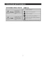
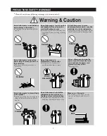
Page 3: ...sts Indicates that a risk of personal injury or material damage exists means Prohibited means Do not disassemble means No contact means The things to be followed means Ground to prevent Electric shock means Power cord should be unplugged from the consent Warning Caution 1 PRECAUTIONS SAFETY WARNINGS ...

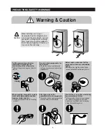
Page 4: ...dicating the permeation of water If there is that kind of trace change the related components or do the necessary treatment such as taping using the insulating tape After repair check the assembled state of components It must be in the same assembled state as before disassembly When repairing completely remove dust and foreign substances from housing wiring joint etc It may prevents fire due to tr...

Page 5: ...t Opening or closing the door may cause things to fall down with may inflict a wound Prohibited Prohibited Prohibited Prohibited Warning Caution Do not allow users to disassemble repair or alter It may cause fire or abnormal operation which leads to injury Do not disassemble Do not allow users to insert the power plugs for many products at the same time May cause abnormal generation of heat or fir...

Page 6: ...IFICATIONS 10 2 3 SPECIFICATIONS 11 2 4 INTERIOR VIEWS 12 2 5 MODEL SPECIFICATION COMPARISON CHART 13 2 6 DIMENSIONS OF REFRIGERATOR INCHES 16 2 7 OPTIONAL MATERIAL SPECIFICATION 17 2 8 REFRIGERANT ROUTE IN REFRIGERATION CYCLE 18 2 PRODUCT SPECIFICATIONS ...

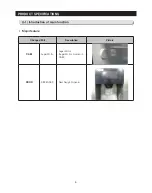
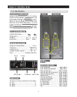
Page 7: ...9 PRODUCT SPECIFICATIONS 2 1 Introduction of main function Major feature Changed Part Description Picture CABI Auger Motor Auger Motor Auger Mortor Located in CABI DOOR DISPENSER New Design Dispener ...

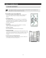
Page 8: ...cooling throughout the refrigerator to maintain optimal temperatures to keep food fresh LED Tower Lighting See everything in a new light with LED tower lighting Clear View Icemaker The Icemaker is located in the freezer door this ensures that all the shelf space can be fully utilized Ice cubes are quickly produced and the clear ice bucket lets you easily see the amount of ice cubes produced Premiu...

Page 9: ...or air circulation AT TOP 2 AT SIDES 2 AT REAR 2 RS25H51 ASSY PCB MAIN DA92 00624 ASSY PCB SUB INVERTER DA92 00215 Thermistor Freezer DA32 10109W Thermistor Freezer Evaporator DA32 00029Q Thermistor Refrigerator DA32 10105U SENSOR TEMP DA32 00029R Thermistor Ambient DA32 10109B Thermistor Ice Maker DA32 00060A SENSOR HUMIDITY DA32 00034B Overload Relay DA34 00004D Fan Motor FRE DA31 00146E Fan Mot...

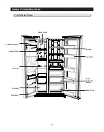
Page 10: ...Maker Bucket Drawers Drawers Shelves Shelves Shelves Lamp Cover Lamp Cover Door Bins Door Bins Door Bins Door Bins Fruit Fruit Vegetable Vegetable Drawer Drawer Water Filter Water Filter Auger motor 12 PRODUCT SPECIFICATIONS ...

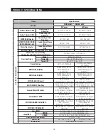
Page 11: ...r 24 7 cu ft 25 4 cu ft Net Dimension W x D x H 36 1 20 x 33 3 4 x 69 15 16 Rated Input Voltage and Frequenc AC 115 127V 60Hz AC 220 240V 50Hz 220V 60Hz Motor Rated Consumption Power 140W Electric Heater Rated Consumption Power AC 120V 513 6W DC12V 17W AC 230V 513 6W DC12V 17W Type of Refrigerator No Frost cooling Refrigerator Refrigerant R134a Refrigerant Input Amount 220 gr 7 76 oz Product Weigh...

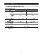
Page 12: ...TOR F SENSOR 502AT 8 F 23 C 5 F 21 C 11 F 24 C 0 F 18 C 3 F 16 C 3 F 19 C 5 F 15 C 8 F 13 C 3 F 16 C Refrigerator Model Temperature Selection ON F C OFF F C THERMISTOR R SENSOR 502AT 34 F 1 C 38 F 3 C 30 F 1 C 37 F 3 C 41 F 5 C 33 F 1 C 44 F 7 C 48 F 9 C 40 F 5 C Defrost Related Components Defrost Cycle First Defrost Cycle Concurrent defrost of F and R 6hr 10min Comp on integation Defrost Cycle FR...

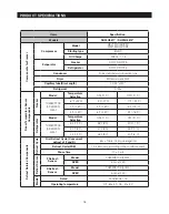
Page 13: ...REP5020LB DC12V CCW 2520rpm 4 3 2W 20 DREP5020LB DC12V CCW 2520rpm 4 3 2W 20 MOTOR BLDC REF DREP5020LD DC12V CCW 1920rpm 4 2 8W 20 DREP5020LD DC12V CCW 1920rpm 4 2 8W 20 MOTOR BLDC Circuit DC 12V CCW 1250rpm 5 1 7W 20 DC 12V CCW 1250rpm 5 1 7W 20 MOTOR BLDC Box Fan G6015S12B DC12V 0 07A 1 0W 2400rpm 7 CW G6015S12B DC12V 0 07A 1 0W 2400rpm 7 CW Geared Motor I M Indoor MVCC18AR19 AC120V 60Hz 18 18rp...

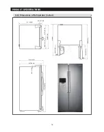
Page 14: ...CT SPECIFICATIONS 908 35 3 4 1169 46 442 17 2 5 549 21 3 5 1295 5 51 512 5 20 1 5 747 29 2 5 919 36 1 5 857 33 3 4 98 3 17 20 386 5 15 1 5 33 5 1 3 10 89 3 1 2 1776 69 9 10 2 6 Dimensions of Refrigerator Inches ...

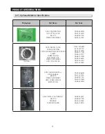
Page 15: ...R PE BAG BAG ENVEL OPE WRENCH SPANNER ASSY PIPE WATER DA97 01469W 6002 000213 DA62 01329A DA65 20110B DA68 00007C DA68 01475B DA69 00484K DA80 00002C DA97 00753D ASSY PACKING INSTALL FIXER HANDLE BAG PE WRENCH SPANNER ASSY LABEL HANDLE INSTRUCTION DA99 03680B DA61 03734A DA69 90113S DA80 00026B DA99 03429H ASSY INSTALL ACCESSORY BAG PE SPANNER SHIM HINGE MID DA99 03490T DA69 90113S DA80 00028A DA6...

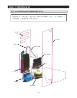
Page 16: ...enser Pipe Hot Pipe Cluster Rear Dryer Capillary Tube Evaporator Suction Pipe Compressor 2 8 Refrigerant Route in Refrigeration cycle Pipe Cluster Rear Suction Pipe Assy Evap Fre Condenser Compressor Capillary Tube Assy Evap Ref Pipe Hot Dryer ...

Page 17: ...TER FILTER TANK OF REFRIGERATOR 29 3 12 DAMPER OF REFRIGERATOR 31 3 13 DOOR BIN OF FREEZER 31 3 14 ICE MAKER COMPARTMENT 32 3 15 PLASTIC DRAWER IN FREEZER 33 3 16 FREEZER SHELF 33 3 17 COVER MULTI IN FREEZER 33 3 18 EVAPOARTOR COVER IN FREEZER 34 3 19 EVAPORATOR IN FREEZER 34 3 20 AMBIENT THERMISTOR 35 3 21 DOOR S W HUMIDITY SENSOR 35 3 22 COMP COOLING FAN 36 3 23 COMP COOLING FAN MOTOR 37 3 24 AS...

Page 18: ...ame status as that before repairing Check the using environment of the refrigerator If the installation is made unstably or the machine is installed in humid conditions or water change its location If grounding seems necessary ground it If there is risk of short circuit due to water or humid conditions be sure to earth Do not plug several devices in one socket Check for breakage press scratch dete...

Page 19: ...ION If a red clip is on the coupler it must be removed before removing the tube After raising the out door insert the supplied SHIM HINGE MIDDLE in the gap between Show case of fridge and the HINGE SHAFT SHIM HINGE MIDDLE are enclosed with the refrigerator The thickness of RING is 1 mm CAUTION Keep the Rings out of the reach of children and make sure that children do not play with them or put them...

Page 20: ...connect the wires 2 3 Remove hinge screws 3 and ground screw 4 counter clockwise and take off the upper hinge 5 along the arrow CAUTION When diassembling make sure the unit is turned off Removing the Lower hinge 1 Remove the door from the lower hinge 1 by carefully lifting the door 2 Remove the lower hinge from the bracket hinge 2 by lifting the lower hinge in the direction of the arrow ...

Page 21: ... Out Door In Door Part name How To Do Descriptive Picture Door Ref Out e g n i h r e p p U e h t g n i v o m e R 1 With the door closed remove the upper hinge cover using a screwdriver 2 Disconnect the wires CAUTION When disassembling make sure the unit is turned off e h t f f o e k a T P P U E G N I H g n i v o m e R 3 3 screw for Removing HINGE UPP 2 CAUTION Be careful not to scratch r o o D e h...

Page 22: ...ng make sure the unit is turned off l a n o g a x e H e v o m e R 3 e g n i h r e p p u e h t g n i v o m e R 3 bolts using a Socket wrench CAUTION When you disassembling with OUT DOOR You don t need to remove HINGE UPP 2 R O O D N I g n i v o m e R 4 Put up a in DOOR after opening the DOOR slightly s y s s A r e p p o t S g n i v o m e R 5 Loosing screws using a screwdriver h c n e r w t e k c o ...

Page 23: ...the Refrigerator Power Cord Disassemble one screw with plus driver as shown in the picture Pull out to the front to disassemble ASSY COVER DISPENSER as shown in the picture Disassemble two remarked sites of housing Disassemble three remarked screws with plus driver Pull out ASSY CASE ICE ROUTE for disassembly ...

Page 24: ...il the molded gasket separates from the door liner CAUTION When you assemble with DOOR You should check the sub Gasket direction Part name How To Do Descriptive Picture Door Handle 1 FRE HANDLE Loose set screw 1 with wrench and lift up the handle 2 REF HANDLE Loose set screw 1 and push the lever On the handle then lift up the handle CAUTION When you assemble the REF HANDLE Push lever 2 on the hand...

Page 25: ...Picture Tempered Glass Shelf These shelves allow storage of larger items and pull out for easy access s e o g t i s a r a f s a t u o f l e h s e h t l l u P 1 2 Lift it up and remove it CAUTION Be car eful of injury Pull out shelf to the direction of arrow for disassembly Only RS25H5611 ...

Page 26: ...ar as it goes 2 Tilt the drawer up and pull it out until it is removed 3 10 Water Filter Part name How To Do Descriptive Picture Water Filter The water filter is located in the lower right hand corner of the refrigerator The water filter for the ice maker and the water dispenser 1 Turn the water filter 1 4 turn counterclockwise and pull it forward 3 9 Gallon Door Bin Part name How To Do Descriptiv...

Page 27: ...SEMBLY 3 11 Water Filter Tank Of Refrigerator Part name How To Do Descriptive Picture Water Filter Tank Remove the screw Remove the fitting clip Remove the water hose by pressing the coupler Remove the screw Remove the screw ...

Page 28: ...30 DISASSEMBLY AND REASSEMBLY Part name How To Do Descriptive Picture Water Tank Separate Water tank from Case water tank Remove the Fitting clip Pull out the Hose by pressing the coupler ...

Page 29: ...in Of Freezer Part name How To Do Descriptive Picture Damper Ref 1 Put driver into the gap between Cover Lamp and Damper 2 Pull out the Cover Lamp Disconnect the wire connector Remove the screw Part name How To Do Descriptive Picture Door Bin In Freezer 1 Push the bin up ...

Page 30: ...ket Assy by holding the handles and pulling up the bottom part slightly Cover I M Lift up the Icemaker Cover and gently pull out Auger Motor Assy Unscrew the 4 screws and disassembly the ASSY ICE MAKER INDOOR as shown Disconnect the hosusing connectors by gently pulling Ice Maker Assy Unscrew the 3 screws Disassembly the Ice Maker Assy ...

Page 31: ...it goes 2 Tilt the drawer up and pull it out until it is removed 3 16 Freezer Shelf Part name How To Do Descriptive Picture Freezer Shelf The shelves slide out for easy access for frozen items 1 Slide the shelf out as far as you can 2 Tilt down and slide it out of the compartment 3 17 Cover Multi In Freezer Part name How To Do Descriptive Picture COVER MULTI IN FREEZER 1 Pull out the screw caps an...

Page 32: ...of freezer to produce cold air driven across the evaporator coils 1 Take off the ductwork in Freezer 2 Disconnect the wire connector Heater Bimental and Thermistor 3 Desolder the inlet and outlet tubes 5 Remove the evaporator 4 Bend the suction pipe 6 Take the same steps to seal the system as mentioned earlier CAUTION When diassembling make sure the unit is turned off Reference How To Do 4 Accumul...

Page 33: ...ermistor sends temperature signals to the micro prosessor Part name How To Do Descriptive Picture Door S W Humidity Sensor 1 Removing the upper hinge With the door closed remove the upper hinge cover 1 using a screwdriver 2 Disconnect the wire CAUTION When diassembling make sure the unit is turned off 3 Removing Cover Hinge sub using a screwdriver 4 Removing Humidity sensor using a screwdriver pus...

Page 34: ... the DRAIN HOSE 3 Remove 1 screw 4 Disengage the HOUSING CONNECTOR Refer to the picture 5 Pull it forward and lean against the DRAIN HOSE 6 Rotate it based on the PIPE 7 The FAN is disassembled Assembly it in reverse order 36 DISASSEMBLY AND REASSEMBLY 3 30 MACHINE COMPARTMENT 3 22 Comp Cooling Fan ...

Page 35: ...ptive Picture Comp Cooling Fan Motor 1 Remove the screw with a flat blade screwdriver 2 Remove the motor fan by pulling the fan out while graping the motor part 3 Unscrew 2 screws fixed in the motor 4 Remove the BRACKET MOTOR with a flat blade screwdriver 5 Remove the MOTOR after pulling the BRACKET MOTOR out ...

Page 36: ...e relay O L with a flat blade screwdriver Refer to the picture Water Valve 1 Unscrew the water valve fixed by the screw 2 Disassemble the white part Pull out the black pin 3 Remove 2 water hose parts while pushing the upper part of Refer to the picture 4 Disengage 2 housing connector parts 5 Remove the hose connected by the nut with a wrench 8mm ...

Page 37: ...3 30 MACHINE COMPARTMENT 3 24 Assy Pba Part name How To Do Descriptive Picture ASSY PCB MAIN Remove 4 Screws Remove the ASSY PCB MAIN ASSY PCB SUB INVERTER Remove the ASSY PCB SUB INVERTER COIL FILTER EMI Remove the COIL FILTER EMI ...

Page 38: ...ame How To Do Descriptive Picture ASSY CASE AUGER MORTOR Push direction 1 Pull direction 2 Remove the screws 4ea by using driver Disconnect housing and Disassembly ASSY CASE AUGER MORTOR 3 30 MACHINE COMPARTMENT 3 25 Assy Case Auger Motor ...

Page 39: ... DIAGNOSIS ERROR DEFECTIVE SENSOR 56 4 14 WHEN ALARM SOUND CONTINUES BUZZER SOUND 57 4 15 WHEN PANEL PBA OPERATES ABNORMALLY 59 4 16 WHEN FAN DOES NOT OPERATE 60 4 17 WHEN THE INTERNAL LAMP OF THE FREEZER FRIDGE DOES NOT LIGHT UP 61 4 18 WHEN CRUSH CRUSHED ICE CUBE CUBED ICE DOES NOT OPERATE WELL 62 4 19 IF ICE MAKER DOES NOT OPERATE 63 4 20 IF ICE WATER IS NOT SUPPLIED 64 4 21 IF WATER IS NOT SUP...

Page 40: ...overload condition 1 3 At this mode the compressor and freezer fan will operate continuously for 24 hours and the refrigerator fan will be on and off according to the set temperature 1 4 After 24 hour operation the system will be cycled at 8 23 for the freezer and 34 1 for the refrigerator 1 5 In order to cancel this mode at any time select the next mode on the ready mode or power off the system 2...

Page 41: ...sly for 5 seconds until a ding dong sound is heard sound is heard 2 Operation 2 1 Most of the system function except the compressor operation are working properly 2 2 There is no defrost cycle in this mode 2 3 OFF is displayed on F R Display 2 4 Cooling O mode is not cleared even if power is reset This function is for display purpose on the r of a show room or a store 1 Mode ON OFF simultaneously ...

Page 42: ...for 8 seconds is acceptable 1 4 After replacement of bad sensor or cancellation of this function this self diagnostics will end 2 Self Diagnostics during the normal operation 2 1 To select this function press Lighting and Energy Saver buttons simultaneously for 8 seconds with an audible tone 2 2 In the self diagnostic mode only corresponding LED segments will be illuminated see the check list on t...

Page 43: ...d Out Defective Motor The voltage should be 7V 12V between MAIN PCB CN75 1 GRAY and 4 YELLOW 22 E FRIDGE FAN ERROR Same as the above The voltage should be 7V 12V between MAIN PCB CN75 1 GRAY and 3 ORNAGE 23 E CONDENSER FAN ERROR Same as the above The voltage should be 7V 12V between MAIN PCB CN75 1 GRAY and 2 SKY BLUE 24 E FREEZER DEFROST ERROR Connector Slipped Out or Open Contact Wire Cut or Sho...

Page 44: ...lly See if the door is being left open for a long time or it there are hot food being put inside When its root causes get cleared it will stop blinking after a while 81 E COMP STARING FAILURE ERROR When the Compressor fails starting 1 It will stop blinking after a while short U V W 2 Check IPM Pins short of Inverter PBA No 1 26 3 Check IPM operating Voltage under DC 13 5V 4 Other cases check the C...

Page 45: ...idge second digit c 4 OVER LOAD MODE Over 34 C Ambient Temp Fridge second digit e 5 LOW TEMP MODE Less than 21 C Ambient Temp Fridge second digit f 6 EXHIBIT MODE Exhibition Mode On Fridge second digit g 7 ICE FULL Bucket Ice Full Fridge first digit d 8 COMPRESSOR COMP On Freezer second digit a 9 FREEZER FAN HIGH F FAN HIGH RPM Freezer second digit b 10 FREEZER FAN LOW F FAN LOW RPM Freezer second...

Page 46: ... the ice type Energy Saver on corresponding models Press Freezer Temp and Lighting buttons simultaneously for 12 seconds to get into this mode In this mode only the display LEDs for temperature will be ON 4 8 Restoration Function for Power Outage 4 9 Set Point Shift Function Press both buttons simultanequsly for 12 seconds Button Function Fridge Option Item Increase LIGHTING Option Item Decrease F...

Page 47: ...5 4 0 C 8 F 1 Freezer Temp Shifting Table Option Value Ex Lowering the Freezer default temp by 3 C Option Item ITEM FREEZER TEMP SHIFT MODEL SAME FOR ALL MODELS OPTION LOCATION FRIDGE TEMP DISPLAY 1 VALUE TEMP VALUE FREEZER VALU 0 0 C 0 F 1 0 5 C 1 F 2 1 0 C 2 F 3 1 5 C 3 F 4 2 0 C 4 F 5 2 5 C 5 F 6 3 0 C 6 F 7 3 5 C 7 F 8 0 5 C 1 F 9 1 0 C 2 F 10 1 5 C 3 F 11 2 0 C 4 F 12 2 5 C 5 F 13 3 0 C 6 F 1...

Page 48: ...ndby time of the Ice Maker ITEM DISPLAY LOCATION FRIDGE TEMP ICE MAKER Ice Ejection Standby Time 3 Standby Time Freezer Display 50min 0 37min 1 35min 2 43min 3 45min 4 47min 5 55min 6 60min 7 40min 8 40min 9 40min 10 40min 11 40min 12 40min 13 40min 14 40min 15 5 Ice Maker Sensor Temp Shifting It is an option shifting the ice ejecting base temperature ITEM DISPLAY LOCATION FRIDGE TEMP Ice Maker Se...

Page 49: ...Y NO RPM CHANGE 0 MINIMUM 2450RPM 1 MINIMUM 2450RPM 2 MINIMUM 2450RPM 3 ITEM DISPLAY LOCATION FRIDGE TEMP MINIMUM COMP RPM SETTING 12 7 Temp Display Option This option is for temp display all on mode If user wants temp display always on this option is solution TEMP DISPLAY OPTION FREEZER DISPLAY NORMAL DISPLAY TEMP DISPLAY TEMPORALLY ON AT USE 0 ALWAYS TEMP DISPLAY ON 1 ALWAYS TEMP DISPLAY ON 2 IT...

Page 50: ...manual Start Normal Replaces FuseAC 250V 6 3A YES Replace the Inverter PCB NO Replace the Inverter PCB NO Replace REG1 7815 NO Replace REG2 5V LDO NO Replace REG3 5V LDO NO 1 Check the wire harness 2 Replace PANELPCB NO Replace the Inverter PCB NO NO YES YES YES YES YES YES YES Caution Is FUSE on PCB Down Is DC 300V applied between both ends of BD1 IS DC 13 2V applied to C121 IS DC 15V applied to ...

Page 51: ...verter PBALED is ON it indicates that the compressor does operate normally 1 Check the COMP Wire 2 Check the Compressor NO NO Replace COMPASS Y YES NO YES YES YES YES 10 minutes have passed since COMP was off When Forced Operation mode is activated COMP operates COMP operation signal CN103 4 6 is High about 2 2 5V Is DC 15V applied to ZD501 F Sensor is Good Temperature sensingpartofMAINPBAis Good ...

Page 52: ...54 TROUBLESHOOTING Diode Voltage of IPM ...

Page 53: ...l Check Thermistor Heater and their contacts Replace the sensor NO Repair the connectors NO YES YES F R DEF Sensor is normal with Self Diagnosis Check Thermistor Heater and their connectors NO YES F R DEF Heater is normal Forced Operation for a certain time NO YES NO NO Defrost Sensor Temp is lower than 5 C Power is supplied to Defrost Heater Repair or Replace defective relays or PBAAss y MAIN PBA...

Page 54: ...BA connector CN30 is inserted properly Replace Thermistor NO YES Ambient Temp Sensor is ok Ambient Sensor Read the resistance between CN30 1 and 2 PBA Thermistor are ok Check the contact of the connector again Start Repair defective contact point or insert the connector properly NO YES 2 When the humidity sensor is defective MAIN PBA Connector CN30 is properly inserted Check wire connection and Ma...

Page 55: ...tor or insert the connector properly NO The connector CN50 is inserted properly YES Replace REED S W NO Door S W is good MAIN PBA DOOR S W are good Separate the Door S W and check its resistance change according to s w on 0Ω and off Ω F Door sensing CN50 8 9 R Door sensing CN50 8 10 R Homebar Door sensing CN50 8 11 Normal State Door Open 5V Door Closed 0V Start Cancel Forced Operation or Forced De...

Page 56: ...unable to hear in case there is heavy noise or built in environment 3 If a buzzer does not sound Start Check Replace a buzzer on Panel PBA NO YES DingDond Sounds when a button on the display panel is pressed Normal YES Door alarm sounds after any of doors are open over 2 min NO Buzzer Breakage Replace Buzzer or Panel PBA YES The Buzzer surface is broken or bended NO YES Buzzer lead comes off from ...

Page 57: ...ive contact NO DOOR PANEL PBA Connector is inserted properly NO Defective PANEL PBA YES It lights up after PANEL PBA replacement Check F R Door Wiring Short or Open Wire Check F R CABI Wiring Short or Open Wire Check Short Open on MAIN PBA or replace it Check F R Door Wiring Short or Open Wire Check F R CABI Wiring Short or Open Wire Check Short Open on MAIN PBA or replace it Cancel Child Lock and...

Page 58: ...V NO YES Pulsesignal FG generatedfromtheFanmotorrotationistransmittedthroughCN75 6 F 7 R 8 C Micomsensesthesesignal IfMicomsensesnosignal MicommakeFanMotorstopfor10secandtrytooperateitagain Micom keepsdoingthesameprocedure4timesuntilMicomreceivethesignal Ifitstillfails MICOMstoptryingfor10minutes Thisprocedurepreventsthemotorfromoverloadwhenforeignsubstancessuchasicebuiltuparoundthe motorrestrictm...

Page 59: ...e output of LED LAMP 12V when Door is open 1 When the DOOR is open the DOOR S W becomes OPEN Micom senses 5V from Door S W and recognizes that the Door is open If 5V has sensed for more than 2 minutes buzzer will sounds DingDong every 1 minute Therefore if the DOOR S W is defective it can generate the Ding Dong sound every 1 minute 2 ON OFF control of the internal lamp is linked with the DOOR S W ...

Page 60: ...Cancel Ice Off Select Cubed Crushed Normal Operation Water Ice S W or Wire Defect MainPBADefect Replaceit Replace SSR74 Normal Operation Water Ice S W or Wire Defect MAIN PBADefect Replace it Replace it RY7C NO Crushed Cubed NO YES YES YES YES NO NO NO Ice comes out when extracting it Ice Selection is Cubed Ice comes out When Water Ice S W is pressed CN50 6 changes to 0V When Water Ice S W is pres...

Page 61: ...Input signal CN90 Pin 4 0V NO 1 Check the wiring connections 2 Replace Ice Maker Kit 3 Replace MAIN PBA NO 1 Replace the Water Valve Refer to the operation condition of Water Valve 2 Replace the Main PBA NO 1 Replace the Ice Maker Sensor Refer to the solution Self Diagnosis error Defective sensor NO YES YES Does Ice Maker rotate when pressing the Ice Maker testing switch over 1 5 sec YES Is the in...

Page 62: ...r Check the connection hose Normal Check Ice water valve hose YES Check soldering short Replace PBA NO Check soldering short Replace PBA NO Check soldering short Replace PBA NO NO YES YES YES Is the confirming sound of the valve operation heard when Ice maker test switch pushed Does Main PBA IC73 4 have high 5V output Does Main PBA IC73 15 have about 0 7V output Is the contact point of Main PBA RE...

Page 63: ...Check the dispensing lever 2 Check switch unit wiring connection 3 Replace PBA NO Check soldering short Replace PBA NO NO YES YES YES YES YES Is the confirming sound of the valve operation heard when dispenser switch pushed Is the valve unit normal Is the voltage of CN50 6 changed 0V 5V according to switch On Off Does Main PBA IC73 6 have about 5V input when switch is on Check soldering short Repl...

Page 64: ...ushed Ice mode selected on the Display PANEL Is the DISPENSER switch selected Does the wiring at the both side of motor connected properly Check the MOTOR Check any interference on MOTOR rotation NO Is the AC input voltage applied to the both ends of the motor Check Repair the Housing connector NO Is the sensing SWITCH connection normal Check Repair the Motor Rotation pressing area NO Is the switc...

Page 65: ...BLESHOOTING DATA1 Temperature table Resistance value and MICOM port voltage of sensor according to the temperature SENSOR CHIP based on PX41C 4 23 Diagnostic method according to the trouble symptom Flow Chart ...

Page 66: ...much food inside so that the food is blocking the outlet vent To keep the refrigerator at a suitable temperature do not fill the refrigerator with too much food and stand by 5 minutes During this 5 minutes RPM command signal is not available it means It means even if available RPM command signal is applied to the compressor it does not work and keep standing by Blinking time is 1 second and dwell ...

Page 67: ...signal to control relays 5 BLDC Fan Control circuit Supplying the power to the fan motor using PWM 6 Inverter Communication circuit Sending operating RPM signal receiving error feedback 7 Step Valve control circuit using motor driver IC to control step valve motor 8 Lamp control circuit Controlling F R room lamp 9 PLC circuit Power Line Communication Circuit 10 Display communication circuit UART a...

Page 68: ...l 2 Inverter Control Circuit Fridge Compressor Control Circuit 3 COMP Driving Feedback CircuitIt receives the COMP operation signals from the Main PBA and feedbacks the inverter errors to the Main PBA 4 BOOTSTRAP Charger It is an independent power circuit for the driving of the IMP High Phase IGBT 5 Current Pickup Circuit It pickups the currents taken by the Shunt resistance and does the PWM DUTY ...

Page 69: ...72 PCB DIAGRAM 6 3 Connector Arrangement Main Board ...

Page 70: ...73 PCB DIAGRAM 6 4 Connector Layout Description Inverter comp control Board Used for Inverter Model ...

Page 71: ...69 5 WIRING DIAGRAM ...

Page 72: ...74 7 1 Block Diagram 7 SCHEMATIC DIAGRAM ...

Page 73: ...75 SCHEMATIC DIAGRAM 7 2 Block Diagram INVERTER PBA DC 13 2V 5V ...

Page 74: ... temperature low quickly and save the power consumption Condensation can occur when you leave the door open for a long time Did you stop the ice making function Is there any ice in the storage unit Is the water pipe connected and the shut off valve open Is the freezer temperature too warm Did you wait for 12 hours after installation of the water supply line before making ice The bubbling comes fro...

Page 75: ...ttom of the freezer clogged Cubes jammed in chute Supply line or shutoff valve is clogged Water filter clogged Dispenser is LOCKED Replace filter cartridge with new cartridge or with plug Check to see if package is holding door open See about the controls This is normal Turn on icemaker or water supply Remove cubes and move the feeler arm to the ON position Break up with fingertip pressure and dis...

Page 76: ...EXPLODED VIEW 1 FREEZER ...

Page 77: ...20 1 SA 2 4 6 DA63 04651B COVERMOTOR BLDC AW PJT PP HB BLACK RM60 1 SA 2 4 7 DA96 00042Q ASSYWIREHARNESS MOTOR ALL 12VDC ALL UL 1 SA 2 4 8 DA63 40167A GROMMET COVERCHIL SI L16 WHITE 1 SA 3 DA63 05335A COVERLAMP FRE SSEDA PP HB NATURAL RJ700 1 SA 4 DA67 02480B CAP ICEDUCT FRE SSEDA HIPS W52 8 L169 6 1 SA 5 DA96 00679L ASSYEVAP FRE SSEDA FRE 120V 218W 2EVA 1 SA 5 1 DA32 00029Q SENSORTEMP DTN C502G6X...

Page 78: ...15 EXPLODED VIEW 2 FRIDGE 16 ...

Page 79: ... FR 4 300 10 WHITE SMAW 1 SA 2 3 DA96 00768B ASSYWIRE HARNESS LED ALL 12VDC ALL UL A 1 SA 2 4 DA63 05532A COVER MULTI REF SSEDA PP COOL WHITE SC 0 1 SNA 2 5 DA62 02580A INSULATION MULTI REF SSEDA VALUE PS FOA 1 SNA 2 6 DA61 06900B PLATE MULTI REF REAR SSEDA PE FOAM T3 0 1 SNA 3 DA63 05342A COVER LAMP REF SSEDA PP NTR 1 SA 4 DA63 05343A COVER LAMP REF MID L SSEDA PP HB NATURAL 1 SA 5 DA63 05344A CO...

Page 80: ...35 3 35 5 35 4 35 6 48 49 50 51 52 53 54 43 44 45 46 47 57 59 12 12 1 12 2 12 4 12 5 12 3 14 3 55 35 56 58 EXPLODED VIEW 3 CABINET 32 35 6 1 35 2 3 35 2 6 35 2 2 35 2 1 35 2 4 35 2 5 60 62 61 ...

Page 81: ...6N ASSYCOVER HINGE UP SSEDA ABS I BLACK 1 SA 13 1 DA34 00043B SWITCH REED 13mm UL1007 AWG22 270 HOOK 1 SA 13 2 DA61 06092A PLATE COVER HINGE SSEDA EGI SECC T0 3 1 SNA 13 3 DA63 05559D COVER HINGE UP L SSEDA ABS 2 5 HB i BLAC 1 SNA 13 4 DA67 03218C CAP INTERLOCK SWITCH HOLE MOUTON PJT ABS 1 SA 14 DA97 15384B ASSYCOVER HINGE UP RIGHT RH5000H EBONY 1 SA 14 1 DA34 00043C SWITCH REED 13mm UL1007 AWG22 ...

Page 82: ...M4 L8 ZPC WHT 6 SA 36 DA97 07852A ASSYCOVER PCB PANEL AW SEM INVERTER 1 SA 37 DA97 15162E ASSYCOVER COMP FSR RH5000H G1 SGCC T0 1 SA 38 DA97 08458G ASSYPIPE CONNECT AW3 4 DOOR 1 SA 39 3903 000786 CBF POWER CORD AT U S A CANADA US3F 1 3C 1 SA 40 DA92 00215C ASSYPCB INVERTER INVERTER AW4 197 98 5m 1 SA 41 DA92 00624D ASSYPCB MAIN ICE WATER RH5000HA 178 197 1 SA 42 DA63 40171D GROMMET SUCT PIPE B RAI...

Page 83: ...1 7 1 8 4 5 7 3 8 2 8 3 11 10 12 EXPLODED VIEW 4 DOOR FRE 4 6 9 3 13 ...

Page 84: ... 2 DA61 06033B SPRINGETC LEVER DISP ICE OPUS1 STS304 1 SA 5 3 DA63 05449A COVER SWITCH AW3 ABS NATURAL HG 0760GP 1 SNA 5 4 DA63 06949A COVER PCB PANEL REAR AW1 12 HIPS NTR 1 SNA 5 5 DA64 04716A INLAY CONTROL RS 5000HA PC BLACK SEGTYP 1 SNA 5 6 DA66 00866L LEVER CASE DISPENSER RS H260A PC 3022IR 1 SNA 5 7 DA92 00626A ASSYMODULE LED TOUCH DISPLAY RS5000HA R 1 SA 5 8 DA96 00106G ASSYWIRE HARNESS DISP...

Page 85: ...3 4 5 1 3 2 2 3 3 3 4 3 4 1 3 1 6 EXPLODED VIEW 5 DOOR REF IN ...

Page 86: ...SA 3 1 6002 001122 SCREW TAPPING FH NO 1 M4 L14 ZPC WHT 2 SC 3 2 DA66 01035A CAM RISERREF MIDUPP FOODSHOWCASE NY 6 1 SA 3 3 6002 001122 SCREW TAPPING FH NO 1 M4 L14 ZPC WHT 3 SC 3 4 DA97 15568A ASSYLEVERHANDLE RH5000H ASSY LEVER 1 SA 3 4 1 6002 000239 SCREW TAPPING TH NO 2S M4 L8 ZPC WHT 1 SA 4 DA97 15449B ASSYGASKET REF SSEDA FSR BLACK 1 SA 5 DA97 15415A ASSYGUARD REF UP RH5000H 3 SA 6 DA97 15415...

Page 87: ...3 3 1 2 1 1 1 4 1 5 1 6 1 7 4 EXPLODED VIEW 6 DOOR REF OUT 1 ...

Page 88: ...00H NONWOVEN T3 L 1 SA 1 4 DA61 03769B MAGNET SVETA MAGNET T5 W15 L18 1 SA 1 5 DA73 00211A RUBBER CAP HOSE i4 PJT SILICON GRAY 1 SA 1 6 DA61 09951A STOPPERDOOR REF LOW FDSR PO SPHC T3 0 B 1 SA 1 7 DA63 07566A GROMMET HINGE REF LOW FOODSHOWCASE PA66 1 SA 2 DA97 15450B ASSYGASKET SSEDA FSR DARK GRAY 1 SA 3 DA97 15014B ASSYHANDLE REF RH5000H ASSY 1 SA 3 1 6002 000213 SCREW TAPPING TH 1 M4 L12 ZPC WHT...

Reviews: