User control functions
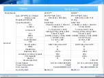
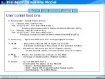
1. Source key : Select Video source
1.1 : Cabinet side Function key
PAL 32”/37”/40” : TV Ext1
→
→
Ext2 AV
→
→
S-Video Component PC HDMI1
→
→
→
→
HDMI2
→
HDMI3 (DTV)
→
1.2 : Remote control Function key
PAL 32”/37”/40” : TV Ext1 Ext2 AV
→
→
→
→
S-Video Component PC HDMI1 HDMI2 HDMI3 (DTV)
→
→
→
→
→
→
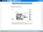
2. Menu key : Open the OSD and Exit the highlighted function.
3. : -
◀ ▶
Moves the selector left or right on the OSD.
- Increase or decrease the values of the selected function
- VOL + : Increase or decrease the level of audio volume.
(in the Anynet mode, You can control only TV volume)
4. :
▼ ▲
Moves the selector up or down on the OSD.
- CH + : Increase or decrease the channel number .
5. Power : 1) Turn ON/OFF the TV.
2) Indicates the status of the Monitor.
- Black : Normal Operation.
- Red : Power Off or Disconnected Signal Cable.
- Red Blinking : PC DPMS Mode.
Ⅱ
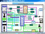
. Inside of Tanzanite Model
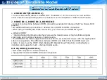
Some Functions of Tanzanite
Some Functions of Tanzanite
Summary of Contents for LE32A Series
Page 1: ...LCD TV Tanzanite TRAINING MANUAL ...
Page 3: ...Ⅰ Understanding of LCD TV UNDERSTANDING OF LCD TV ...
Page 12: ...Ⅱ Inside of Tanzanite Model Inside of Tanzanite Model ...
Page 17: ...Ⅱ Inside of Tanzanite Model Control Connection Panel Control Connection Panel ...
Page 48: ...DECODER D61211GM Ⅱ Inside of Tanzanite Model ...
Page 55: ...SOUND AMP NTP3100 Package 56 pin MLF 8mm by 8mm Ⅱ Inside of Tanzanite Model ...
Page 56: ...SOUND AMP NTP3100 PIN DESCRIPTIONS Ⅱ Inside of Tanzanite Model ...
Page 57: ...DTV COMP SW BA7657 BLOCK DIAGRAM Ⅱ Inside of Tanzanite Model ...
Page 59: ...BOARD DESCRIPTION Ⅲ Board description ...
Page 61: ...CONTROL SPEAKER JACK MAIN BOARD LAYOUT MAIN BOARD LAYOUT ...
Page 67: ...Ⅲ Board description IP SPEC IP SPEC MAIN BOARD LAYOUT MAIN BOARD LAYOUT ...
Page 68: ...Ⅲ Board description IP SPEC IP SPEC MAIN BOARD LAYOUT MAIN BOARD LAYOUT ...
Page 69: ...Ⅲ Board description IP SPEC IP SPEC MAIN BOARD LAYOUT MAIN BOARD LAYOUT ...
Page 70: ...Ⅲ Board description IP SPEC IP SPEC MAIN BOARD LAYOUT MAIN BOARD LAYOUT ...
Page 71: ...Ⅲ Board description IP SPEC IP SPEC MAIN BOARD LAYOUT MAIN BOARD LAYOUT ...
Page 72: ...Ⅲ Board description IP SPEC IP SPEC MAIN BOARD LAYOUT MAIN BOARD LAYOUT ...
Page 75: ...IV Disassembly DISASSEMBLY ...
Page 76: ...IV Disassembly Disassembly Tanzanite ...
Page 77: ...IV Disassembly ...
Page 78: ...IV Disassembly ...
Page 79: ...IV Disassembly ...
Page 80: ...IV Disassembly ...
Page 81: ...V Trouble Shooting TROUBLE SHOOTING ...
Page 87: ...V Trouble Shooting ...
Page 88: ...V Trouble Shooting R G B Output Signal ...
Page 89: ...V Trouble Shooting Digital Output Data Signal of HDMI Data ...
Page 90: ...V Trouble Shooting CVBS Output Signal Tuner CVBS Output Signal ...
Page 91: ...V Trouble Shooting Digital Output Data Analog Signal Y C ...
Page 92: ...V Trouble Shooting The Signal Inputed to IC2002 The Signal Inputed to IC2001 ...
Page 93: ...V Trouble Shooting ...
Page 94: ...HOW TO UPGRADE ...
Page 101: ...ATTACHMENT ...
Page 102: ...CONTENTS CONTENTS I What is HDMI II What is a TrusurroundXT ...
Page 104: ...HDMI block diagram What is HDMI Attachment ...
Page 106: ...Connector Drawings All dimensions in millimeters What is HDMI Attachment ...
Page 108: ...HDMI Encoder Decoder Overview What is HDMI Attachment ...
Page 110: ...Example TMDS periods in 720x480p video frame What is HDMI Attachment ...

