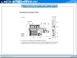
Control & Connection Panel
Control & Connection Panel
Ⅱ
. Inside of Tanzanite Model
3
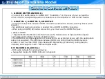
ANT IN
To view television channels correctly, a signal must be received by the set from one of
the following sources:
-An outdoor aerial / A cable television network / A satellite network
4
EXT 1, EXT 2
-Inputs or outputs for external devices, such as VCR, DVD, video game device or video
disc players.
5
COMON INTERFACE Slot (DTV Only)
- When not inserting "CI CARD" in some channels, "Scrambled Signal" is displayed on the
screen.
- The pairing information containing a telephone number, CI CARD ID, Host ID and other
information will be displayed in about 2~3 minutes. If an error message is displayed,
please contact your service provider.
-When the channel information configuration has finished, the message "Updating
Completed" is displayed, indicating that the channel list is now updated.
★
You must obtain a CI CARD from a local cable service provider. Remove the CI CARD
by carefully pulling it out with your hands since dropping the CI CARD may cause
damage to it.
★
Insert the CI-Card in the direction marked on it.
Summary of Contents for LE32A Series
Page 1: ...LCD TV Tanzanite TRAINING MANUAL ...
Page 3: ...Ⅰ Understanding of LCD TV UNDERSTANDING OF LCD TV ...
Page 12: ...Ⅱ Inside of Tanzanite Model Inside of Tanzanite Model ...
Page 17: ...Ⅱ Inside of Tanzanite Model Control Connection Panel Control Connection Panel ...
Page 48: ...DECODER D61211GM Ⅱ Inside of Tanzanite Model ...
Page 55: ...SOUND AMP NTP3100 Package 56 pin MLF 8mm by 8mm Ⅱ Inside of Tanzanite Model ...
Page 56: ...SOUND AMP NTP3100 PIN DESCRIPTIONS Ⅱ Inside of Tanzanite Model ...
Page 57: ...DTV COMP SW BA7657 BLOCK DIAGRAM Ⅱ Inside of Tanzanite Model ...
Page 59: ...BOARD DESCRIPTION Ⅲ Board description ...
Page 61: ...CONTROL SPEAKER JACK MAIN BOARD LAYOUT MAIN BOARD LAYOUT ...
Page 67: ...Ⅲ Board description IP SPEC IP SPEC MAIN BOARD LAYOUT MAIN BOARD LAYOUT ...
Page 68: ...Ⅲ Board description IP SPEC IP SPEC MAIN BOARD LAYOUT MAIN BOARD LAYOUT ...
Page 69: ...Ⅲ Board description IP SPEC IP SPEC MAIN BOARD LAYOUT MAIN BOARD LAYOUT ...
Page 70: ...Ⅲ Board description IP SPEC IP SPEC MAIN BOARD LAYOUT MAIN BOARD LAYOUT ...
Page 71: ...Ⅲ Board description IP SPEC IP SPEC MAIN BOARD LAYOUT MAIN BOARD LAYOUT ...
Page 72: ...Ⅲ Board description IP SPEC IP SPEC MAIN BOARD LAYOUT MAIN BOARD LAYOUT ...
Page 75: ...IV Disassembly DISASSEMBLY ...
Page 76: ...IV Disassembly Disassembly Tanzanite ...
Page 77: ...IV Disassembly ...
Page 78: ...IV Disassembly ...
Page 79: ...IV Disassembly ...
Page 80: ...IV Disassembly ...
Page 81: ...V Trouble Shooting TROUBLE SHOOTING ...
Page 87: ...V Trouble Shooting ...
Page 88: ...V Trouble Shooting R G B Output Signal ...
Page 89: ...V Trouble Shooting Digital Output Data Signal of HDMI Data ...
Page 90: ...V Trouble Shooting CVBS Output Signal Tuner CVBS Output Signal ...
Page 91: ...V Trouble Shooting Digital Output Data Analog Signal Y C ...
Page 92: ...V Trouble Shooting The Signal Inputed to IC2002 The Signal Inputed to IC2001 ...
Page 93: ...V Trouble Shooting ...
Page 94: ...HOW TO UPGRADE ...
Page 101: ...ATTACHMENT ...
Page 102: ...CONTENTS CONTENTS I What is HDMI II What is a TrusurroundXT ...
Page 104: ...HDMI block diagram What is HDMI Attachment ...
Page 106: ...Connector Drawings All dimensions in millimeters What is HDMI Attachment ...
Page 108: ...HDMI Encoder Decoder Overview What is HDMI Attachment ...
Page 110: ...Example TMDS periods in 720x480p video frame What is HDMI Attachment ...

