Operating Modes Overview
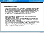
The HDMI link operates in one of three modes: Video Data Period, Data Island
period, and Control period. During the Video Data Period, the active pixels of
an active video line are transmitted. During the Data Island period, audio and
auxiliary data are transmitted using a series of packets. The Control period is
used when no video, audio, or auxiliary data needs to be transmitted.
A Control Period is required between any other two periods.
Video Data Periods use transition minimized coding to encode 8 bits per
channel, or 24 bits total per pixel.
Data Island Periods are encoded using a similar transition minimized coding,
TMDS Error Reduction Coding (TERC4), which transmits 4 bits per channel,
or 12 bits total per pixel clock period.
During Control Periods, 2 bits per channel, or 6 bits total are encoded per pixel
clock using a transition maximized encoding. These 6 bits are HSYNC, VSYNC,
CTL0, CTL1, CTL2 and CTL3. Near the end of every Control Period,
a Preamble, using the CTLx bits, indicates whether the next Data Period is
a Video Data Period or a Data Island Period.
What is HDMI?
Attachment
Summary of Contents for LE32A Series
Page 1: ...LCD TV Tanzanite TRAINING MANUAL ...
Page 3: ...Ⅰ Understanding of LCD TV UNDERSTANDING OF LCD TV ...
Page 12: ...Ⅱ Inside of Tanzanite Model Inside of Tanzanite Model ...
Page 17: ...Ⅱ Inside of Tanzanite Model Control Connection Panel Control Connection Panel ...
Page 48: ...DECODER D61211GM Ⅱ Inside of Tanzanite Model ...
Page 55: ...SOUND AMP NTP3100 Package 56 pin MLF 8mm by 8mm Ⅱ Inside of Tanzanite Model ...
Page 56: ...SOUND AMP NTP3100 PIN DESCRIPTIONS Ⅱ Inside of Tanzanite Model ...
Page 57: ...DTV COMP SW BA7657 BLOCK DIAGRAM Ⅱ Inside of Tanzanite Model ...
Page 59: ...BOARD DESCRIPTION Ⅲ Board description ...
Page 61: ...CONTROL SPEAKER JACK MAIN BOARD LAYOUT MAIN BOARD LAYOUT ...
Page 67: ...Ⅲ Board description IP SPEC IP SPEC MAIN BOARD LAYOUT MAIN BOARD LAYOUT ...
Page 68: ...Ⅲ Board description IP SPEC IP SPEC MAIN BOARD LAYOUT MAIN BOARD LAYOUT ...
Page 69: ...Ⅲ Board description IP SPEC IP SPEC MAIN BOARD LAYOUT MAIN BOARD LAYOUT ...
Page 70: ...Ⅲ Board description IP SPEC IP SPEC MAIN BOARD LAYOUT MAIN BOARD LAYOUT ...
Page 71: ...Ⅲ Board description IP SPEC IP SPEC MAIN BOARD LAYOUT MAIN BOARD LAYOUT ...
Page 72: ...Ⅲ Board description IP SPEC IP SPEC MAIN BOARD LAYOUT MAIN BOARD LAYOUT ...
Page 75: ...IV Disassembly DISASSEMBLY ...
Page 76: ...IV Disassembly Disassembly Tanzanite ...
Page 77: ...IV Disassembly ...
Page 78: ...IV Disassembly ...
Page 79: ...IV Disassembly ...
Page 80: ...IV Disassembly ...
Page 81: ...V Trouble Shooting TROUBLE SHOOTING ...
Page 87: ...V Trouble Shooting ...
Page 88: ...V Trouble Shooting R G B Output Signal ...
Page 89: ...V Trouble Shooting Digital Output Data Signal of HDMI Data ...
Page 90: ...V Trouble Shooting CVBS Output Signal Tuner CVBS Output Signal ...
Page 91: ...V Trouble Shooting Digital Output Data Analog Signal Y C ...
Page 92: ...V Trouble Shooting The Signal Inputed to IC2002 The Signal Inputed to IC2001 ...
Page 93: ...V Trouble Shooting ...
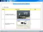
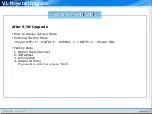
Page 94: ...HOW TO UPGRADE ...
Page 101: ...ATTACHMENT ...
Page 102: ...CONTENTS CONTENTS I What is HDMI II What is a TrusurroundXT ...
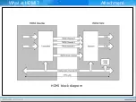
Page 104: ...HDMI block diagram What is HDMI Attachment ...
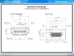
Page 106: ...Connector Drawings All dimensions in millimeters What is HDMI Attachment ...
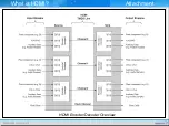
Page 108: ...HDMI Encoder Decoder Overview What is HDMI Attachment ...
Page 110: ...Example TMDS periods in 720x480p video frame What is HDMI Attachment ...

